ROBOMASTER Development Board Type C
User Manual
© 2020 DJI All Rights Reserved.
11
卧式
VCC_3V3
UART6_RX[6]
UART6_TX[6]
C12347pF50V0201
D22PESD5V0F1BL
C A
C12447pF50V0201
R129
33.0R 0201
R130
4.7KR
0201
J29
1WF03-245003-00000
1
1
2
2
3
3
4
4
5
5
D21PESD5V0F1BL
C A
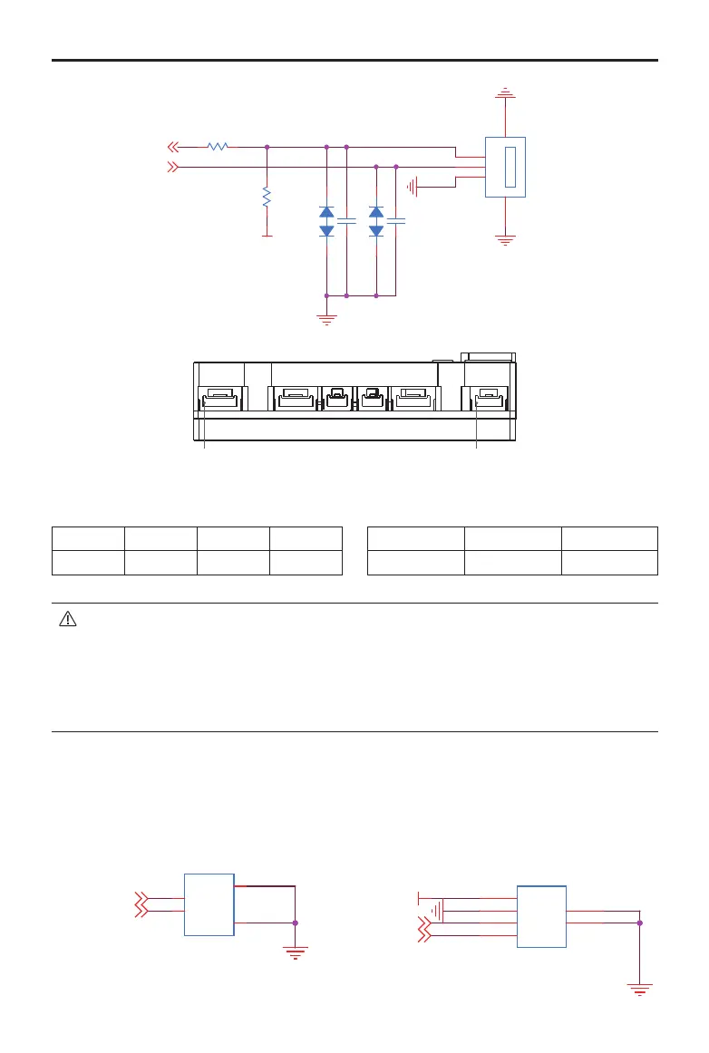
Pin1 (UART1) Pin1 (UART6)
UART 1 pin:
1 2 3 4
RXD TXD GND 5V
UART 6 pin:
1 2 3
GND TXD RXD
• Since the line sequences of the UART6 port and Referee System’s Power Management
Module are the same, the TX and RX cables must be intersected when the Board Type C
communicates with the Power Management Module.
• The silk-screen UART1 and UART2 on the shell of the Board Type C do not correspond with
the serial port conguration of the STM32. UART1 corresponds with UART6 of the SMT32
and UART2 corresponds with UART1 of the STM32.
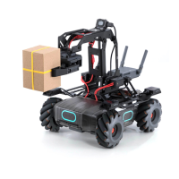
CAN Ports
The Board Type C has two CAN ports. CAN1 port is a 2-pin port and CAN2 is a 4-pin port. The CAN
ports support a maximum transmission speed of 1 Mbps and can be used to control the RoboMaster
ESC or communicate with other devices.
卧式
卧式
VCC_5V
CAN1_L[4,8]
CAN1_H[4,8]
CAN2_H[4,8]
CAN2_L[4,8]
J23
1.25T-7-2AW
1
1
2
2
3
3
4
4
J22
1.25T-7-2AW
1
1
2
2
3
3
4
4
J20
1.25T-7-4AW
1
1
2
2
3
3
4
4
5
5
6
6
J21
1.25T-7-4AW
1
1
2
2
3
3
4
4
5
5
6
6
Horizontal
Horizontal
Horizontal