ROBOMASTER Development Board Type C
User Manual
© 2020 DJI All Rights Reserved.
15
VCC_5V
TIM4_CH3[5]
C84
10uF
0603
R40 510R
0402
R42
10K
0402
D5
1N4148
A
C
Q5
1
2
3
LS1
A
C
NC
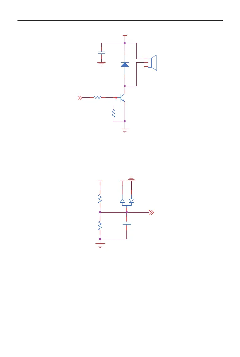
Voltage Detection
The voltage detection can be used to detect the input voltage VCC_BAT. After being divided, the
voltage connects to ADC (PF10) of the SMT32. D10 clamps the voltage and protects the ADC port of
the STM32.
VCC_3V3
VCC_BAT
ADC_BAT
R83
22.0KR
0201
R72
200.0KR
0201
C89
100.0nF
0402
D10
BAV99
1
2
3
6-Axis Inertial Measurement Unit (IMU)
A high-performance 6-axis IMU is integrated into the Board Type C. The IMU uses a BMI088 that
boasts an excellent seismic performance and a unique damping design that greatly improves the
reliability of the gyroscope when impacted during operation. To prevent temperature drift, a heating
circuit has been added to the Board Type C. The temperature of the gyroscope can be maintained
constantly via the TIM10_CH1 (corresponding IO is PF6) of the STM32. The heating circuit is shown
below. When the heat power is 5 V and the TIM10_CH1 maintains a high level, the heating power is
0.58 W and the recommended temperature should be 15° to 20° C higher than the normal operating
temperature of the circuit board.
The communication method of STM32 and BMI088 is SPI, which supports a maximum communication
rate of 10 MHz. The schematic diagram is shown below.