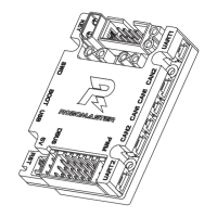
ROBOMASTER Development Board Type C
User Manual
6
© 2020 DJI All Rights Reserved.
One 24 V to 5 V step-down circuit (power network VCC_5V), which is used for the onboard device
power supply and as the second input of power supply. The maximum output current is 1 A.
One 5 V (power network VCC_5V) to 3.3 V step-down circuit, which is mainly used for the onboard
device power supply.
Input Protection Circuit
The XT30 is adopted as the power input port for the Board Type C. The Board Type C prevents
reverse connection and slow startup, and with a built-in circuit for input overvoltage protection, it will
turn off the second circuit when the input is higher than 28 V.
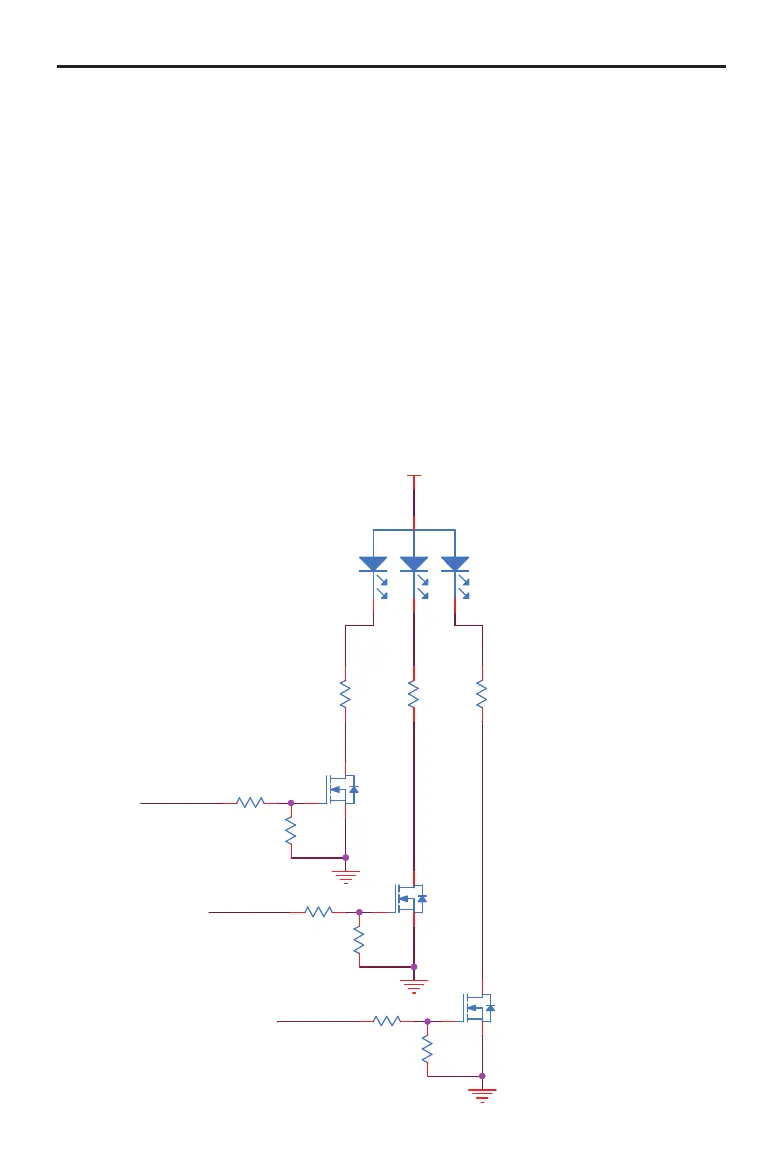
Customizable LED
The Board Type C has a common anode RGB LED and the corresponding control IO is PH10 (Blue),
PH11 (Green), and PH12 (Red). When the output level of the IO port is high, the corresponding status
LED will be on. When the output level is low, the LED will be off. The brightness of the LED can be
adjusted via the PWM control.
LED_B
LED_G
LED_R
VCC_5V
R179
3.3KR
0402
R
G
B
D12
1
2
3
4
R107
10.0KR
0201
Q8
YJL3400A
G
S D
R106 1.0KR
0402
R177
2.0KR
0402
Q9
YJL3400A
G
S D
R108 1.0KR
0402
R178
5.6KR
0402
Q7
YJL3400A
G
S
D
R110
10.0KR
0201
R101
10.0KR
0201
R100 1.0KR
0402