ROBOMASTER Development Board Type C
User Manual
16
© 2020 DJI All Rights Reserved.
IIC Address: 0x0E
附近2mm内不布器件,远离功率线
VCC_3V3_IMU
VCC_3V3_IMU
VCC_3V3_IMU
DRDY_IST8310[6]
I2C3_SDA[4]
I2C3_SCL[4]
RSTN_IST8310[6]
R124
4.7KR
0402
R125
4.7KR
0402
C109
100nF
0402
C105 4.7uF
0603
C104
100nF
0402
U11
IST8310
SCL
1
AVDD
2
NC1
3
NC2
4
CAD0
5
CAD1
6
VPP
7
NC3
8
GND1
9
C1
10
GND2
11
NC
12
DVDD
13
RSTN
14
DRDY
15
SDA
16
TP10
1
TP11
1
PS接GND:使用SPI模式
PS接VDD:使用IIC模式
VCC_3V3_IMUCS1_Gyro
CS1_Accel
SPI1_MOSI
SPI1_CLK
SPI1_MISO
INT1_Accel
INT1_Gyro
U1
BMI088
SDI
9
SDO1
15
VDD
3
GNDIO
4
CSB2
5
GND
6
PS
7
SCK
8
SDO2
10
CSB1
14
NC
2
VDDIO
11
INT4
13
INT3
12
INT2
1
INT1
16
TP5
1
TP1
1
TP3
1
TP4
1
C1
100.0nF
0402
TP2
1
R1 33.0R
0402
C2
100.0nF
0402
Load Imax:116.3mA
走线请按照至少500mA
PGND1
Heat_Power
TIM10_CH1
R14 120.0R
0402
Q3
YJL3400A
G
S D
R10430.0R
0402
R9430.0R
0402
R8430.0R
0402
R11430.0R
0402
R6430.0R
0402
R4430.0R
0402
R2430.0R
0402
R13
10K
0402
R7430.0R
0402
R5430.0R
0402
R3430.0R
0402
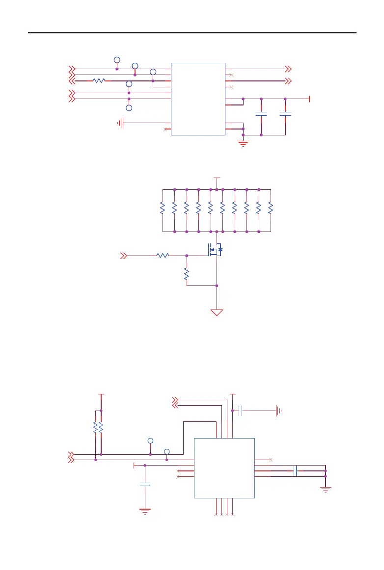
Magnetometer
The 3-axis magnetometer chip IST8310 is integrated into the Board Type C. The communication
method of STM32 and IST8310 is IIC, which supports a maximum communication rate of 400 kHz.
The default IIC address of IST8310 is 0x0E. The schematic diagram is shown below.
PS connects GND: SPI mode
PS connects VDD: IIC mode
Load Imax: 116.3 mA
The operating current should be at least 500 mA
The chip should be far away from the power
cable and no device is allowed within 2 mm.