ROBOMASTER Development Board Type C
User Manual
© 2020 DJI All Rights Reserved.
7
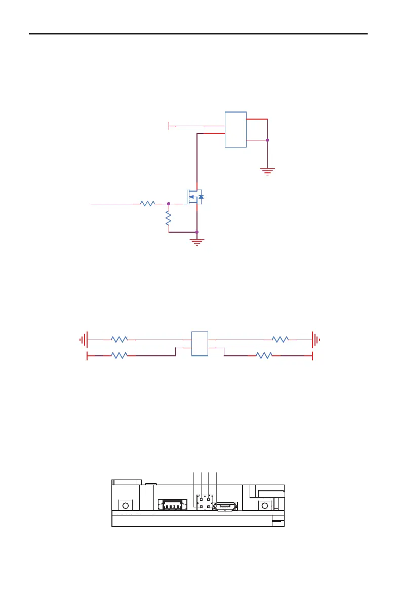
5V Port
The controllable 5V power port can be connected to the RoboMaster Red Laser Sight. The
corresponding switch control IO of the port is PC8. The brightness of the RoboMaster Red Laser Sight
can be adjusted via the PWM control.
TIM3_CH3
VCC_5V
R41
10K
0402
J5
53398-0271
1
1
2
2
3
3
4
4
Q4
YJL3400A
G
S D
R39 510R
0402
BOOT Conguration Port
The STM32 chip on the Board Type C has two pins: BOOT0 and BOOT1. The STM32 has three boot
methods and the level status of the two pins when the chip is reset determines the boot method after
the chip is reset. The Board Type C’s BOOT conguration schematic diagram is shown below.
BOOT1 BOOT0
VCC_3V3VCC_3V3
R165 10K
R1661.0KR
R64 10K
R167 1.0KR
J31
12
34
The level of the two BOOT pins is set to low by default. When powered on, STM32 boots from user
ash memory. The reset level status of BOOT0 and BOOT1 can also be congured using jumpers. As
shown below, the BOOT conguration pin is pinned out by using 2 x 2 rows of pin headers spaced 2.54
mm apart. For example, when BOOT0 = 1 and BOOT1 = 0, STM32 boots from the system memory
and enters DFU (Device Firmware Update) mode. Refer to the Micro USB Port section for more
information.
1 234