Digital Monitoring Products
CellCom‑LTE‑V
Programming and Installation Guide
12
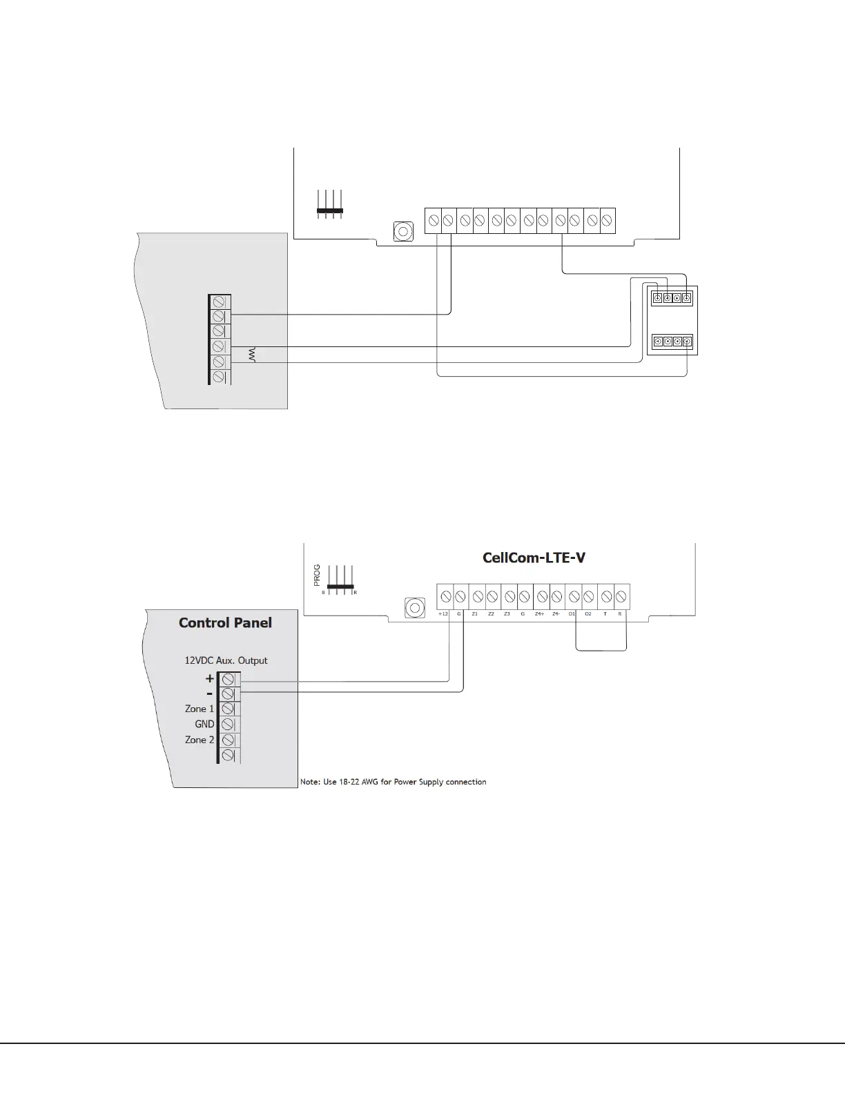
Using Outputs for Communication Failure
When the programmed output turns on and trips the control panel zone, a communication failure is indicated at the
control panel, notifying the user. Program the output number (O1 or O2) in communication failure output within the
output options programming menu. See Communication Failure Output for programming instructions. See Figure9a
for wiring instructions.
Rev 4 Level E Hardware Only
When wired as shown in Figure 9, with Output1 programmed as the Communication Failure Output, a Communication
Failure from the communicator will put the ring terminal to ground which will cause the host panel to display a
communication failure as it normally would. See Figure9b.
Note: Use 18-22 AWG for Power Supply connection
12VDC Aux. Output
+
-
CellCom-LTE-V
PROG
+12 G Z1 Z2 Z4-Z4+GZ3 RTO2O1
NO
RB
GND
Zone 1
Zone 2
Control Panel EOL resistor
NC C NEG-
NO
NC C POS+
Control Panel
Relay
Module
Figure 9a: Communication Failure Zone Connection
Figure 9b: Rev 4 Level E Hardware Connection