Digital Monitoring Products
CellCom‑LTE‑V
Programming and Installation Guide
10
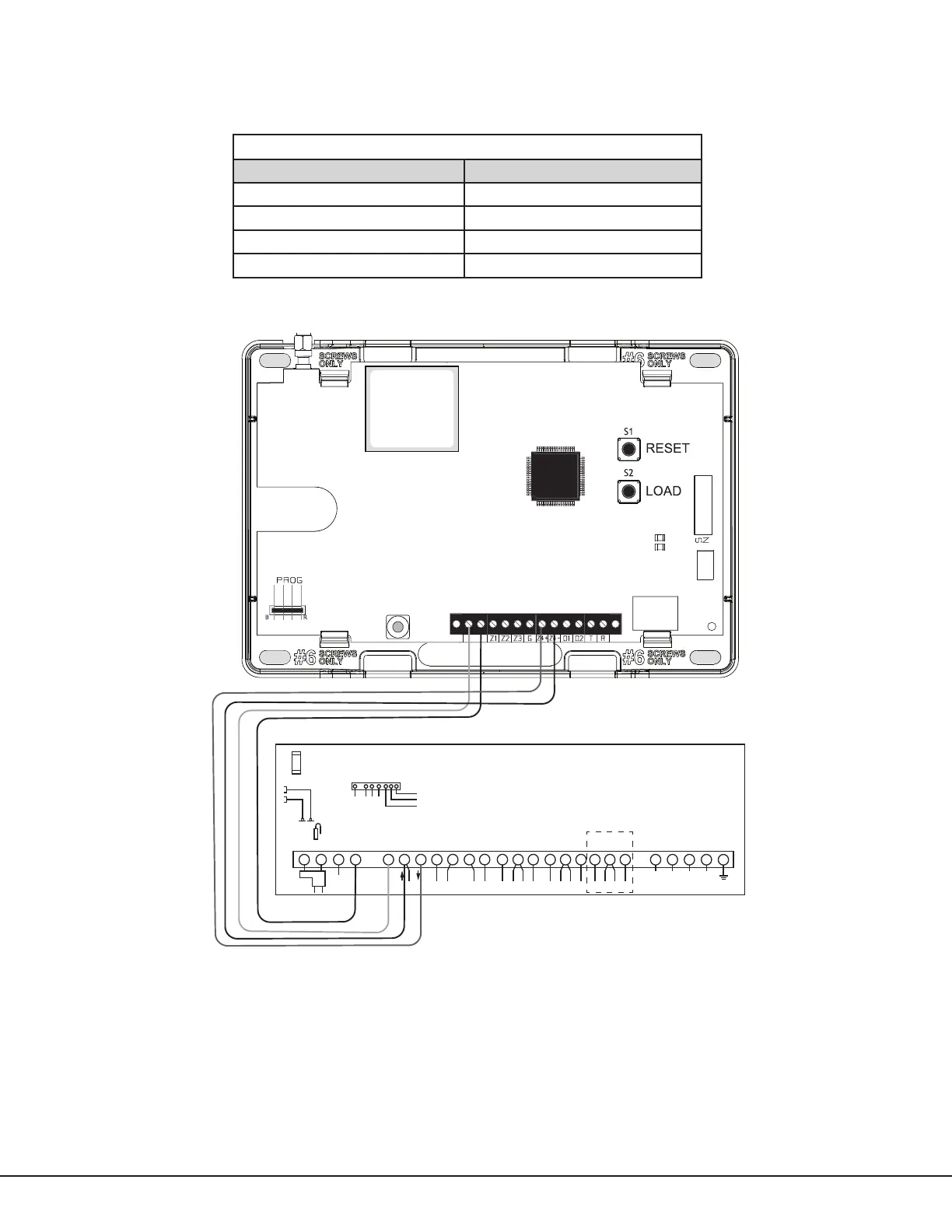
Ademco/Honeywell ECP Connection
The communicator can be connected to the ECP Bus of an Ademco/Honeywell panel. See Table3 and Figure8 for the
necessary wiring connections for CellCom‑LTE‑V to communicate with the Ademco/Honeywell ECP Bus.
Communicator to ECP Wiring
Communicator Ademco/Honeywell ECP Bus
+DC Keypad Power
‑DC Keypad GND
Z4+ Data Out
Z4‑ Data In
Table 3: Communicator to Ademco/Honeywell ECP Wiring
1 2 3 4 5 6 7 8 9 10 11 12 13 14 15 16 17 18 19 20 21 22 23 24 25
+ +-
HI
HI
HI
LO
LO
LO
LO
HI
HI
LO
LO
HI
HI
LO
LO
HI
TIP
(BROWN)
RING
(G RAY )
TIP
(GREEN)
RING
(RED)
+
-
BLACK
RED
SYNC
COM
DATA
(USE SA4120XM-1
CABLE)
1 2 3 4 5 6 7 8
OUT 17
+12 AUX
GND
OUT 18
VISTA 20P ONLY
Ademco Vista 20P
+DC-
Figure 8: Ademco Vista 20P ECP to CellCom‑LTE‑V
ECP operation must be enabled when programming the communicator. See Keypad Input in System Options. When
connected as shown in Figure8, the communicator provides the following operations:
• Arm and disarm the Ademco/Honeywell panel for Stay/Away systems using the VirtualKeypad™app and
VirtualKeypad.com.
• Receives alarm, trouble, and opening/closing messages from the panel and sends them to the central station.
• Add, delete, and change user codes in the Ademco/Honeywell panel.