Digital Monitoring Products
CellCom‑LTE‑V
Programming and Installation Guide
6
APPLICATIONS
The communicator can be used in a variety of applications.
CID Dialer Connection
Connect the tip and ring from the control panel directly to the communicator to capture Contact ID messages that are
based on the SIA communication standard DC‑05‑1999.09‑DCS. These messages are then formatted into a serial3
message and sent to a DMP Model SCS‑1R or SCS‑VR receiver. CID Dialer Connection cannot be used when using
Zone4 Bell Connection. Do not connect telephone company wires to the communicator. Remove any connected
telephone company wires from the control panel. See Figure4.
Zones 1‑4 Input Connection
Connect each control panel relay output to a zone on the communicator. For programming purposes, the zone
numbers are 1‑4. The following are examples of how you might use this application for a burglary or fire alarm.
Burglary
Use a normally closed output on a burglary control panel to indicate a burglary alarm. The communicator zone should
be programmed with a zone name and burglary zone type. When the output on the control panel turns on and trips
the communicator zone, a message is sent to an SCS‑1R or SCS‑VR receiver at the central station. The zone name
programming can be used to describe which control panel zone indicated a burglary. See Figure5a.
Note: Zone4 can only be used as a standard input zone when not programmed as zone type Auxiliary2 (A2). See
Zone4 Bell Connection.
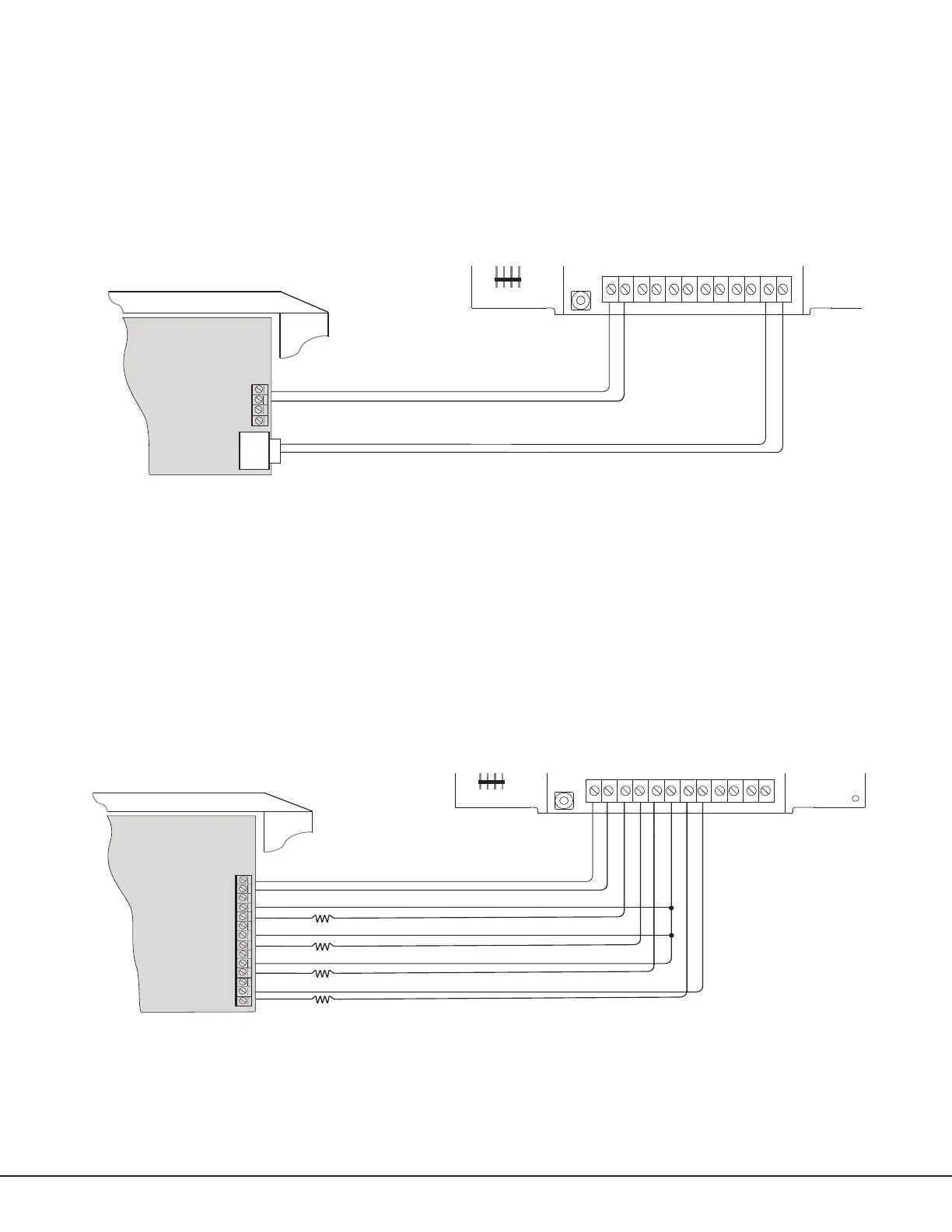
Figure 4: Wiring Diagram for Tip and Ring Connection
Use 18-22 AWG for
Power Supply connection
CONTROL PANEL TIP
CONTROL PANEL RING
12VDC Aux. Output +
-
Ground
Control Panel
The panel or separate power
supply must be 12 Volt Regulated
and Power Limited.
Telephone
Jack
Connector
BELL -
BELL +
+12 G Z1 Z2 Z4-Z4+GZ3 RTO2O1
RB
J9
S3
Use 18-22 AWG for
Power Supply connection
Z3 +
Z4 +
Z4 -
GND
12VDC Aux. Output
+
-
Ground
Burglary
Control Panel
The panel or separate power
supply must be 12 Volt Regulated
and Power Limited.
Z1 +
Z2 +
RESET
S1
LOAD
S2
PROG
S
N
+12 G Z1 Z2 Z4-Z4+GZ3 RTO2O1
RB
Normally Open
Common
Normally Closed
Normally Open
Common
Normally Closed
Normally Open
Common
Normally Closed
Normally Open
Common
Normally Closed
J8
J9
S1
S2
S3
1k ohm
1k ohm
1k ohm
1k ohm
MODEL
CellComSLC
Figure 5a: Wiring Diagram for Burglary Zones 1‑4