6500-065-J-7-18
3
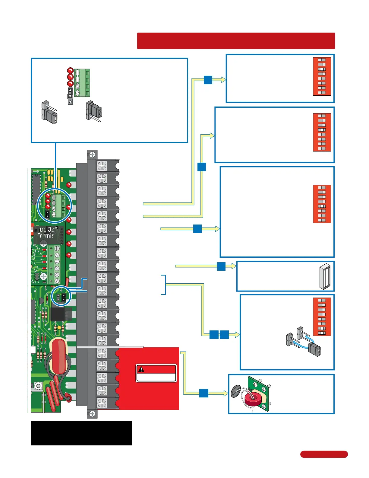
QUICK GUIDE: Terminal Descriptions
See pages 27 and 28 for
terminal wiring.
NC NO
2
4
5
6
7
8
20
OB
CB
OE
CE
G
G
1477-010
3 4
1
2
3
4
20
19
18
17
16
15
14
13
12
11
10
9
8
7
6
5
4
3
2
1
DANGER
HIGH VOLTAGE!
Low Voltage Common
Full Open
24 VAC - 250 mA max.
Full Open
Full Open
Standard Reverse
Gate Tracker Data
Gate Tracker Busy
24 VDC Mag Lock Power
Dry Relay Contact
Dry Relay Contact
Low Voltage Common
Low Voltage Common
Entrapment Alarm
Alarm Reset
Secondary Current Sensor
Motor
Motor
Circuit Board Power
Circuit Board Power
20-Pin Main Terminal
4
5
6
9
10
11
16
For dual operator applications
ONLY. Allows the secondary
reversing sensor to monitor
the current flow into the
secondary operator. See page
25 for more information.
24-volt DC magnetic lock power is
provided constantly except when the
gate is opening or open (Normally
Closed function). 1 Amp Max.
• lf SW 1, switch 3 is ON, functions as a
normal full open input (Normal setting).
• lf SW 1, switch 3 is OFF, input to
terminal #4 becomes the output from the
EXIT loop detector plugged into the EXIT
loop port. (Used for specialized functions).
SW 1
1
ON
2 3 4 5 6 7 8
SW 1
1
ON
2 3 4 5 6 7 8
• When gate is closed, input will open gate.
• When gate is open and auto close timer SW 1,
switch 4 is turned ON, input will re-set and hold
timer.
• When gate is open and auto close timer SW 1,
switch 4 is turned OFF, input will close gate.
• When gate is closing, input will reverse gate.
SW 1
1
ON
2 3 4 5 6 7 8
This input ONLY functions when gate is
fully opened or in the closing cycle.
• When gate is closing: SW 1, switch 5 is
OFF, an input to terminal #6 will stop and
reverse and the gate to the full open position.
Note: If the auto-close timer is ON, when gate
reaches the open position, timer will not
close the gate. Another input command is
needed to reset and close the gate (Normal
Setting).
• SW 1, switch 5 ON, an input to terminal #6
(e.g.: external loop detector connected) becomes a
SHADOW loop input. It is only active when the gate is
fully opened.
Open LED
Close LED
Stop LED
Open N.O.
Close N.O.
Stop N.C.
Common
4-Pin Non-Removable Terminal
1
2
3
4
Jumper on bottom
2 pins when using
4-pin terminal.
Jumper on top 2 pins
when NOT using
4-pin terminal.
Notes:
• Use a standard 4-wire 3-button
control station.
DoorKing’s 3-wire 3-button
control station cannot be used.
• When using a 3-button control
station AND a interlock device
together, #3 terminal (N.C.) must
be wired in series.
• See page 27 for wiring.
3-Pin with
Jumper
Relay
Contacts
Operation of the circuit board dry
relay contact is dependent on
setting of SW 1, switches 7 and 8.
Relay contacts can be set for
Normally Open (NO) or
Normally Closed (NC)
operation.
Contact rating is
1 amp maximum
at 24-volts DC.
NO
NC
SW 1
1
ON
2 3 4 5 6 7 8
Relay Not Available when using DoorKing
plug-In shadow loop detector.
UL 325
Terminal
Pages 16,17,28
(See note below)
Terminal #3 Note:
Exceeding 250 mA of power from this terminal may
cause the circuit board transformer to overheat,
causing intermittent problems.
Quick Guide - 2