1.
2.
4
A
B
1
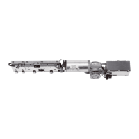
5. Insert the end caps onto the spacers.
6. Insert the spacers with the end caps into the casing.
Ensure the correct mounting position; the spacers and
end caps must be installed as shown in figure 4.
7. Align everything so that the end caps are flush with the
casing on both sides.
2
2. Screw the lever to the sliding piece.
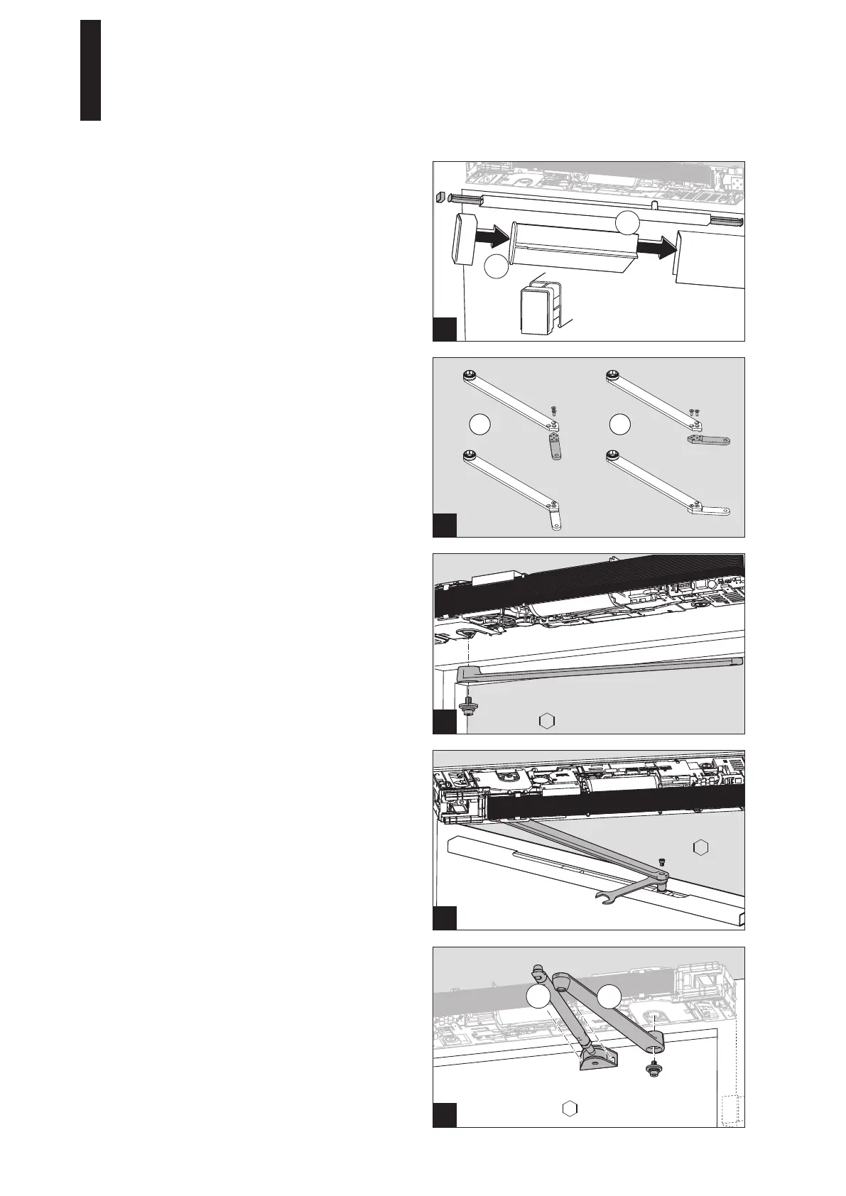
5.10 Mounting the standard arm assembly
1. Screw the tensioning screw (A) with 2 screws into the
prepared holes.
2. Screw the lever (B) using a high tightening torque (35
Nm) to the drive shaft.
Use only the supplied self-locking screw. If this screw
is loosened during repair or maintenance work, it needs
to be replaced with a new self-locking screw.
1
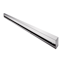
5.8 Mounting the slide channel lever CPD
In case the slide channel lever CPD is used, the lever must
be assembled.
1. Screw together the lever according to the mounting
position.
1 Hinge side DIN right and
opposite hinge side DIN left
2 Hinge side DIN left and
opposite hinge side DIN right
1
5.9 Mounting the lever
1. Screw disk using a high tightening torque (35 Nm) to
the drive shaft.
Use only the supplied self-locking screw. If this screw
is loosened during repair or maintenance work, it needs
to be replaced with a new self-locking screw.
1 2
35 Nm
35 Nm
5 mm
5 mm
5 mm
SW 13 mm
ED 100, ED 250
—
22

 Loading...