2.
1.
2
1
B
A
1
1.
2.
3
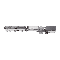
3. Align the tensioning screw perpendicular to the door
panel with the door closed.
4. Loosen the counternut on the tensioning screw.
5. Screw or unscrew the tensioning screw until the
tensioning screw is perpendicular to the door panel in
the clipped together state of the arm assembly.
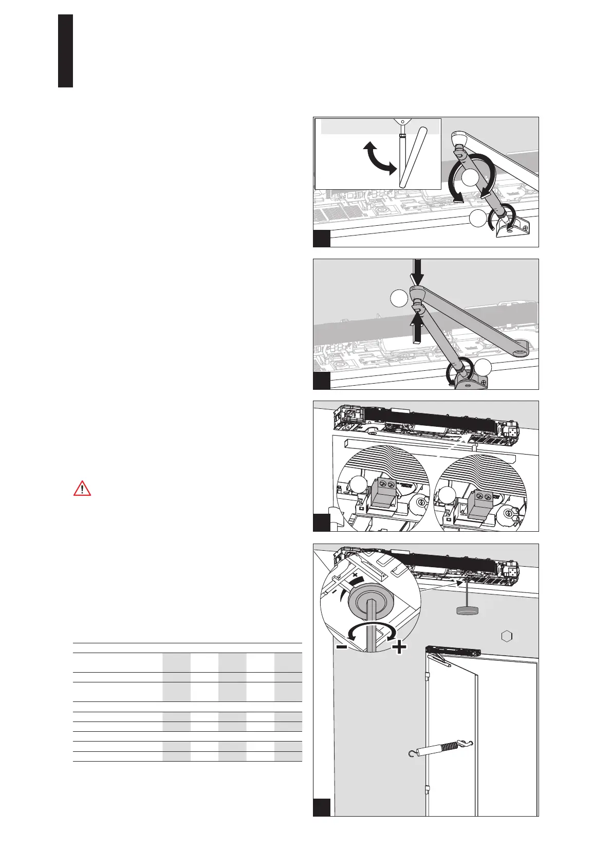
5.12 Adjusting the spring force
The spring is not tensioned when delivered. A primary
tension of at least 10 rotations is required for the operation.
The adjustment will be tested during the teach-in run. The
teach-in run will be aborted if the spring force is too low. A
new teach-in run must be carried out if the spring has been
readjusted.
1. Refer to the table to find the required rotations for the
spring adjustment and adjust the spring force.
Selection EN class
Door panel width in
mm
850 950 1100 1250 1400
EN class EN 2 EN 3 EN 4 EN 5 EN 6
Min. closing torque in
case of 2°
13 Nm 18 Nm 26 Nm 37 Nm 54 Nm
Rotations for the spring adjustment
ED 100 10 14 16 -- --
ED 250 -- -- 14 18 24
Possible combination arm assembly
Standard arm assembly X X X X X
Slide channel X X X X X
The table shows approximate values. You must
therefore test and correct, if necessary, the closing
torque at 2° in accordance with EN 1154. In case of
lintel depths larger than 300 mm, you must also check
the minimum closing torque between 88° – 92°.
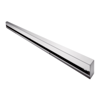
5.11 Setting the braking circuit
1. Ensure that the mains voltage is disconnected.
2. Insert the connector depending on the type of
installation.
(A) = installation pulling
(B) = installation pushing
The braking circuit will not be effective if the
connector is not correctly connected. The door can
close with a high speed.
6. Push the ball head of the tensioning screw into the
receiver on the lever.
7. Tighten the counternut.
5 mm
90°
ED 100, ED 250
—
23

 Loading...