3.6.3 Key switch button ST 32 DCW
Key left > 3s: A connected DCW program switch
switches to off and the red LED is on.
Key right
< 3s:
Night/bank pulse
Key right
> 3s:
A connected DCW program switch
switches to automatic and the green LED
is on.
3.6.4 I/O module DCW
Address: 00 (DIP switch position)
In 1 – In 4 are without function
Functions for Out 1 to Out 4 (adjustable via hand terminal)
0 No function 4 Door closed and locked
1 Door is closed 5 Information or error
2 Door is open 6 Larger than door angle x°
3 Error
Factory setting:
Out 1 4 Out 2 2 Out 3 5 Out 4 6
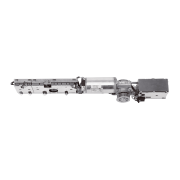
3.7 Technical data
Application conditions
Ambient temperature - 15 – + 50 °C
Only for dry rooms Relative air humidity max.
93 %
non-condensing
Power supply 230 V AC +10 %/-15 %,
50 Hz
Protection class IP 20
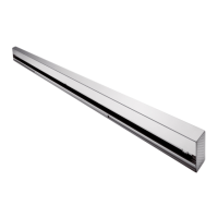
General
Dimensions (WxHxD) 685 x 70 x 130 mm
Min. clearance between hinges
2-panel
1,400 mm
Min. clearance between hinges
2-panel with ESR
1,450 mm
Min. clearance between hinges
2-panel with VARIO casing
1,500 mm
Drive unit weight 12 kg
Power supply for external
consumers
24 V DC +/- 5 %, 1,5 A
Door opening angle Max. 95° – 110°
depending on the type of
installation
Fuse protection provided by the
customer
16 A
Operating noise Max. 50 dB(A)
Inputs
Connecting terminals Max. 1.5 mm
2
Potential-free activator Internal and external
(NO contact)
Night/bank
(intercom)
8 – 24 V DC/AC + 5 %
Night/bank (key switch) Make contact/
NO/NC contact
Safety sensor BS and BGS (NC contact)
Test signal safety sensor BS and BGS
Shutdown drive function (door
lock switch)
NC contact/
NO contact
Outputs
Connecting terminals max. 1.5 mm
2
Potential-free status contact Door closed
Door open
Error
Door closed and locked
Integrated functions
Latching action Force is adjustable
Hold-open time in case of
automatic opening
0 – 30 seconds
(optional 0 – 180 seconds)
Hold-open time night/bank 0 – 30 seconds
Hold-open time in case of
manual opening
0 – 30 seconds
Blocking behavior Reversing/
door closing function
Unlocking time door opener 0 – 4 seconds
Locking response Motor lock
Wind load control Up to 150 N
Voltage independent
braking circuit
Adjustable with
potentiometer
LED status display green
red
yellow
- Operating control voltage
- Error message
- Service interval display
Integrated program switch Off
Automatic
Permanent open
Exit only (only for
1-panel systems)
User interface with
information display
Status display and
parameterization
Slot for
Upgrade Cards
Extension of the
functional range
Update interface Update firmware
TMP – Temperature
Management Program
Overload protection
IDC – Initial-Drive-Control Driving cycle optimization
Cycle counter 0 – 1,000,000
(meaningful division)
Power assist function Servo assist in case of a
manual opening
Push & Go function Door opening in case of a
manual movement of 4°
ED 100, ED 250
—
7

 Loading...