DORMA AUTOMATICES, Inc. 924 Sherwood Drive Toll-Free: 877-367-6211 Subject to change without notice
DL3463-050 08/2016 Lake Bluff, IL 60044 Fax: 847-249-3999
ED100 / ED250 SERVICE MANUAL
—
13
> 3s Reset
< 3s Quit
> 3s
PRG
< 3s
LEARN
Fact-Setup
> 3s
> 8s
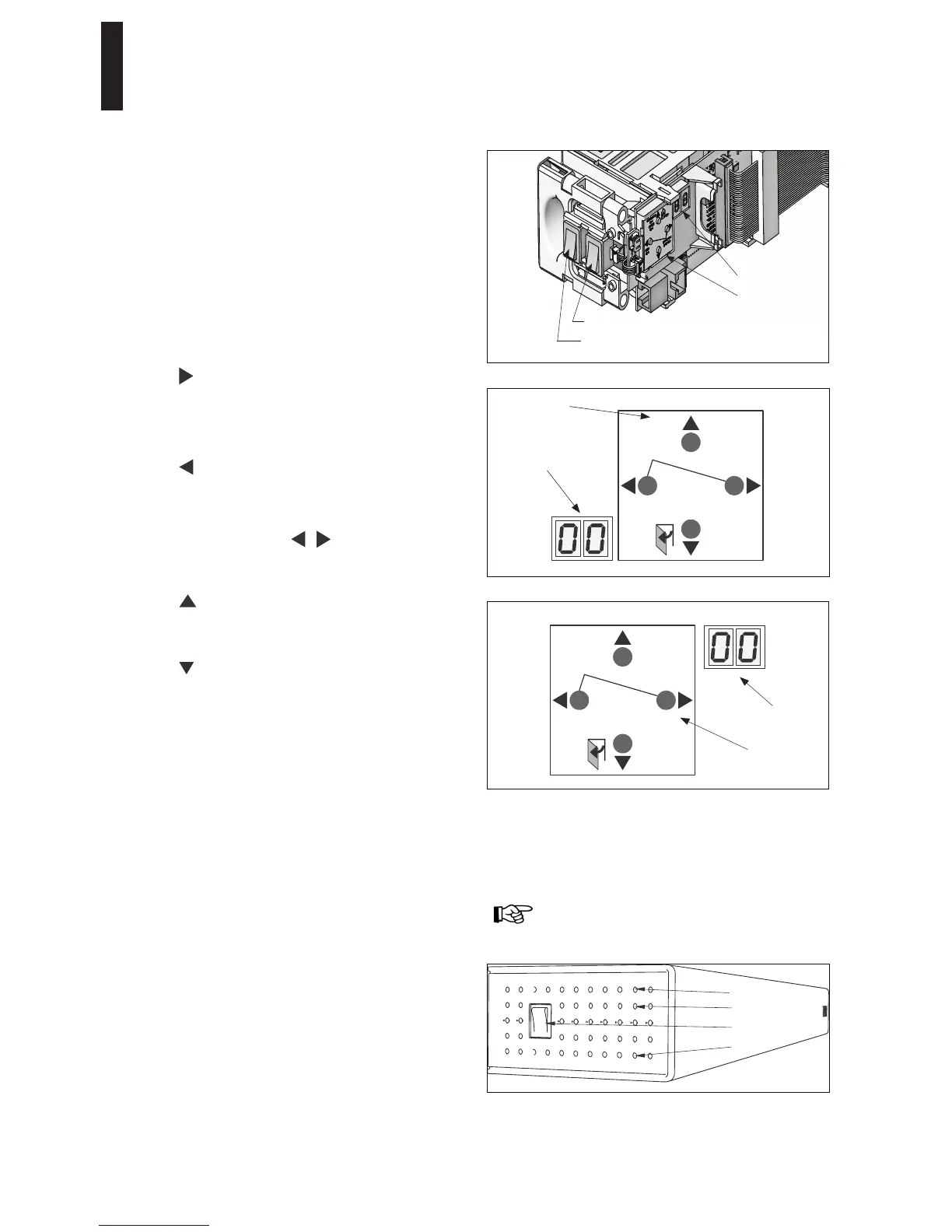
Button legend
User interface: RH door
Information display
Internal program switch - 2 pole
4 button keypad
2 digit display
Internal program switch - 3 pole
> 3s Reset
< 3s Quit
LEARN
< 3s
> 3s
Fact-Setup
PRG
> 3s
> 8s
User interface: LH door
Button legend
Information display
7 User interface
Operator is equipped with a user interface to input and adjust
door parameters (Section 17), and to display information and
error codes (Section 18). User interface consists of:
Four button keypad
2 digit information display
Four button keypad
Button functions are adapted to installation orientation of
operator; each of the 4 buttons always has same function
according to how buttons are arranged.
Button legend can be removed and rotated.
Buttons perform the following functions:
Right
Call up parameter menu – press button > 3s PRG.
Change selected parameter.
Save changed value.
Left
Cancel parameter change process.
Exit parameter menu – press button < 3s Quit.
Left and right together
Acknowledge errors – press both buttons < 3s.
Reset – press both buttons > 3s.
Up
Scroll through parameters and error messages.
Increase parameter value.
Down
Scroll through parameters and error messages.
Decrease parameter value.
Opening pulse – press button < 3 seconds.
Learning cycle – press button >3s LEARN,
program switches off.
Reset with factory setting – press button > 8s Fact-Setup,
program switches off.
Reference Section 18, SL parameter - Factory setting
level.
Adjust direction of installation following a power off/on
reset.
Status LEDs on power switch side of operator
Red LED: Blinking codes are used to indicate "ln __"
information or certain error codes "E _ _".
Details on each display code, or LED status, can be
found in troubleshooting chart in Section 19.
Yellow LED: Maintenance interval indicator. When
illuminated, it is an indication operator system has to be
serviced. Maintenance interval is adjustable by DORMA
service.
Green LED: ON – Indicates internal 24VDC power on.
OFF – Indicates internal 24VDC power off.
Green
Power switch
Yellow
Red
Refer to first commissioning section in single or
double door installation manuals for display format
orientation.
2-digit information display
Display is configured during commissioning so that numbers
and digits are displayed correctly without regard to installation
orientation.