DORMA AUTOMATICES, Inc. 924 Sherwood Drive Toll-Free: 877-367-6211 Subject to change without notice
DL3463-050 08/2016 Lake Bluff, IL 60044 Fax: 847-249-3999
ED100 / ED250 SERVICE MANUAL
—
33
19 Diagnosis / troubleshooting
Overview
DORMA operators meet high safety standards and comply
with all required technical rules and requirements. Operator-
monitors internal as well as external safety circuits that are
managed / monitored by the operator.
While operator is in use, certain situations may develop that
cause error messages.
Operator attempts to identify the cause and respond accordingly.
The response depends on severity of error and may vary from
a simple notification to deactivating the operator's automa-
tic function. In this case, operator will switch to emergency
mode and act like a door closer. Users can then access door
manually.
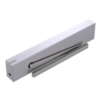
> 3s Reset
< 3s Quit
> 3s
PRG
< 3s
LEARN
Fact-Setup
> 3s
> 8s
User interface display, or the Dorma hand-held terminal, can
display:
Information “In” codes.
Error message codes which are stored in “E0” to “E9”
memory.
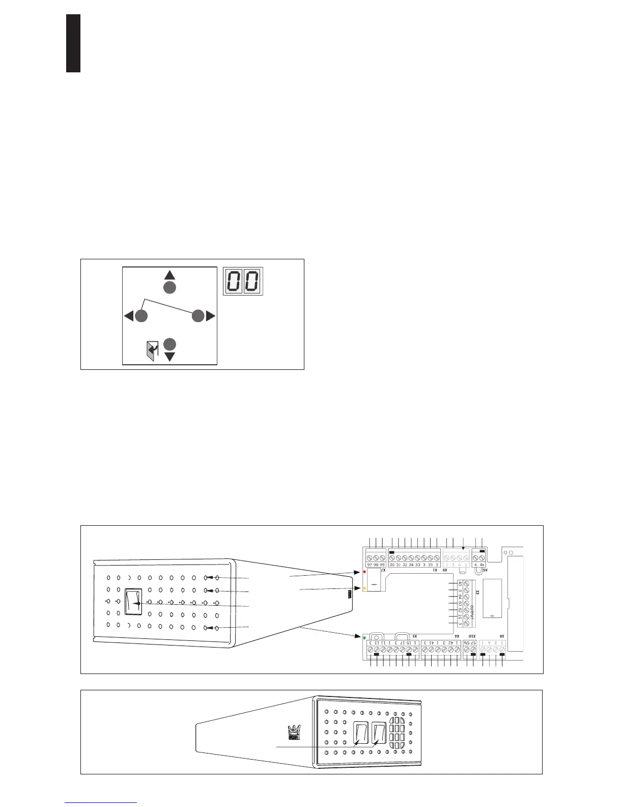
Red LED adjacent to power switch displays a blinking code for
certain ln information and for error messages.
Refer to:
Information "ln".
Troubleshooting chart.
Information (“In”)
"Ln" information codes are provided to facilitate servicing of
operator. These codes indicate both faulty system status as
well as operating situations that interrupt automatic function
of operator system.
Examples:
In 11 -> Hold open system was triggered.
In 01 -> Door is obstructed by an obstacle and door
movement was stopped by operator.
If an Information message occurs several times, it can be
turned into an error message.
Addressing error message codes stored in “E0” to “E9”
Error messages indicate a possible hardware defect. However,
installation errors and manual operation during safety tests
can also cause error messages, so system switches to
emergency mode.
Resetting error messages: following are options available for
resetting error messages:
Switching both program switches to OFF.
User interface Reset button
Reset system by pressing Reset button on user interface
> 3 seconds (cover must be removed to access user
interface) (v1.8 firmware).
Power reset
Switch off the power switch. Switch it back on again
after 10 seconds.
Always analyze and remove cause for error before respective
error message is reset. The troubleshooting chart is intended
as a guide for diagnosing errors.
Red LED
Yellow LED
Power switch
Green LED
Connection board
Program switches