DORMA AUTOMATICES, Inc. 924 Sherwood Drive Toll-Free: 877-367-6211 Subject to change without notice
DL3463-050 08/2016 Lake Bluff, IL 60044 Fax: 847-249-3999
ED100 / ED250 SERVICE MANUAL
—
41
21 Quick start guide
DORMA USA
924 Sherwood DriveToll-Free: 877-367-6211
PED
Lake Bluff, IL 60044 Fax: 877-423-7999 2 April 2013
Email: automatics@dorma-usa.com www.dorma-usa.comSubject to change without notice
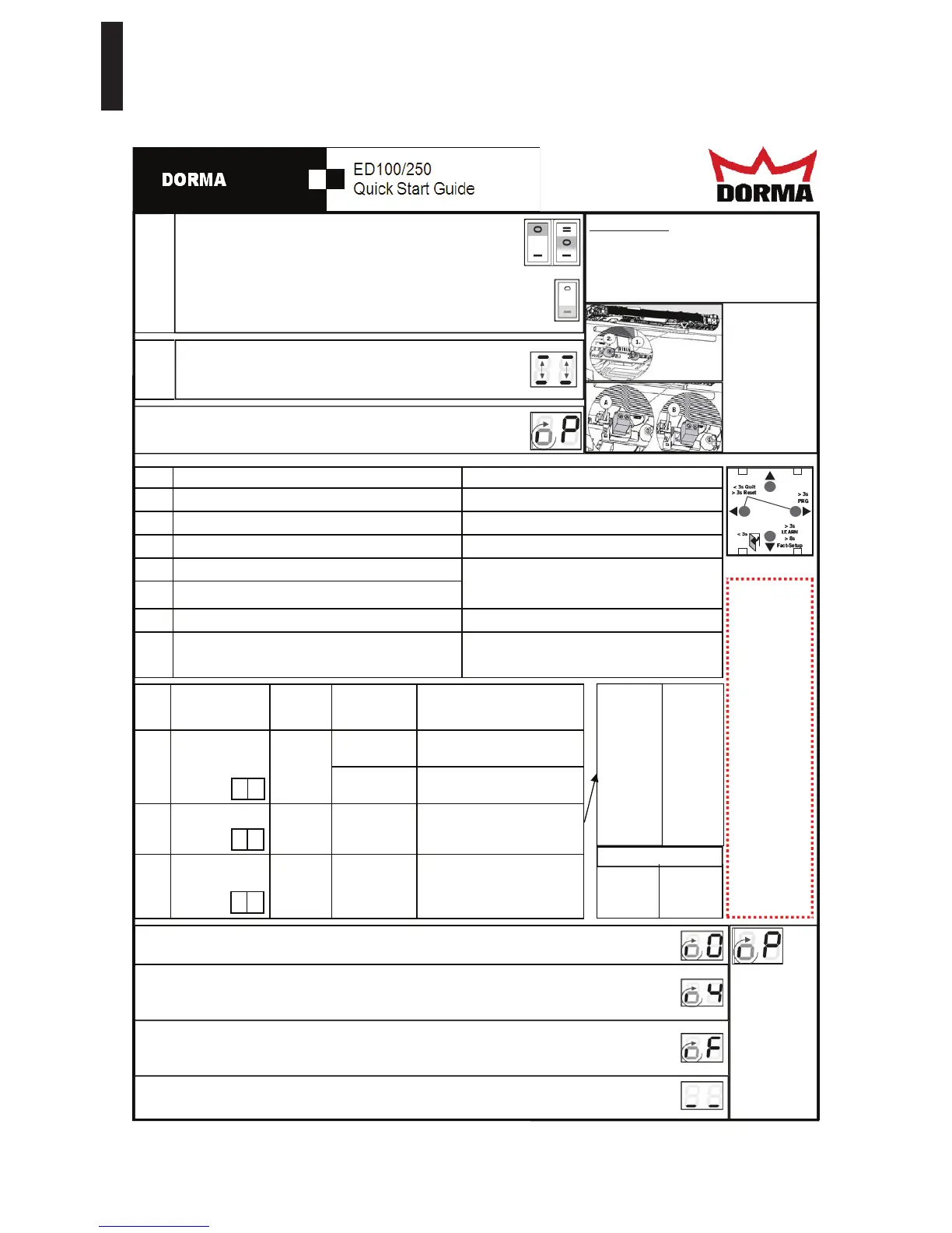
The operator must be completely installed and the door must be
closed. The arm must be installed according to the installation direc-
tions. All terminal blocks need to be installed with no safety sensors
connected. Both Program switches need to be in "0" position.
Then switch on the power supply, a series of numbers and letters will show
on the display. This will stop after two horizontal dashes side by side move
up and down several times.
While the dashes are moving up and down, push the bottom button on
the display . This will identify which way the unit is mounted. Letters
and numbers will now display right side up
.
STEP
1
STEP
2
A "0" displayed on the right side and a rotating segment on the left indicates the unit is ready for a Learn Cy-
cle. To start the learn cycle: Push and hold the bottom button for 3 seconds, until the display changes.
-3= -1 1/8"
-2= -3/4"
-1= - 3/8"
0=0
1= 3/8"
2= 3/4"
3= 1 1/8"
4= 1 1/2"
5= 1 7/8"
6= 2 1/4"
7= 2 5/8"
8= 3"
STEP CONFIGURATION
RANGE
FACTORY
SETTINGS
Units
[ ]=
factory setting
DESCRIPTION
10 Door arm type
Push or Pull
Mounting
[0] Operator installed on the pull
side (hinge side)
1 Operator installed on the push
side (non hinge side).
11 Reveal -3 to 30
ED250
-3 to 50
[0] The reveal depth is adjusted in
steps of 3/8". (Ex: 4 = 1 1/2")
12 Door Width 7 to 11
ED250
7 to 15
[10] The astragal is included in the
door width. The door width is
indicated in steps of 4".
(Ex. 9 = 36") (Ex. 11= 44”)
0 to 1
A S
The display will show a “P” on the right with a rotating segment on the left.
STLUSER DETCEPXE SNOITCERID PETS
3 Push and hold the right button for three seconds Parameter ID will appear (ex: AS)
)00 :xe( gnittes tnerruc eht yalpsid lliW niaga nottub thgir eht hsuP 4
gnittes tnerruc eht hsalf lliw yalpsiD niaga nottub thgir eht hsuP 5
6 Use the up and down buttons to change the settings
7 Push the right button again to accept the changes
8 Push the left button again to go back to the menu
9 Push the down button to go to the next setting (or)
Push the left button again to exit programming menu
Go back to step 4 under programming.
Display will show a rotating segment and a “0”
All three required settings must be made to flash
even if the value does not need to be changed be-
fore the door will move to the learn cycle.
If a "P" is dis-
played again on
the right side,
the systems
requires further
settings. Reset
the previous 3
settings,
steps 3 - 12.
Remember they
all have to flash.
If the door stops and displays "F", this is an indication that the spring force is too low. Turn off the power and
push or let the door close. Increase the spring force and restart the learn cycle by pushing the bottom button for
3 seconds. The spring should have a minimum of 10 turns and a maximum of 18 to 24 turns. (24 on ED250)
The operator will complete the Learn cycle. When finished there will be two horizontal bars side by side
on the display. You can now continue with the programming and customize the door as desired.
9= 3 3/8"
10= 3 3/4"
11= 4 1/8"
12= 4 1/2"
13= 4 7/8"
14= 5 1/4"
15= 5 5/8"
16= 6"
24= 9”
32= 12”
40= 15”
48= 18’
IMPORTANT:
Verify the no power closing speed and jumper
setting before programming the door and
completing a learn cycle. The door must be
adjusted to close in no less than 3 seconds
but a minimum of 5 seconds is recommend.
7= 28”
8= 32”
9= 36”
10= 40”
11= 44”
12= 48”
DOOR SIZES
The door will make several movements and the display will cycle through several letters and numbers. When it
stops at “4” push the door open to the desired opening angle between 90 and 110 degrees, then let go of the
door and push the bottom button momentarily to continue the learn cycle.
Notice:
This guide is
intended to be
used as a refer-
ence to assist
a trained and
certified
AAADM
technician in
programming
the DORMA
ED100/250
operator in
accordance
with ANSI
A156.19 Stan-
dard for Low
Energy Auto-
matic Doors or
ANSI 156.10
for Full Power
Automatic
Doors
r d
r b
When the jumper
is in the correct
position the door
will push open
easily and close
slowly. If the
door is very hard
to push open
change the
jumper position
 Loading...