SD-2
15
7
5
14
13
12
11
10
9
1
6
4
3
2
8
SD-2
15
7
5
14
13
12
11
10
9
1
6
4
3
2
8
SD-2
15
7
5
14
13
12
11
10
9
1
6
4
3
2
8
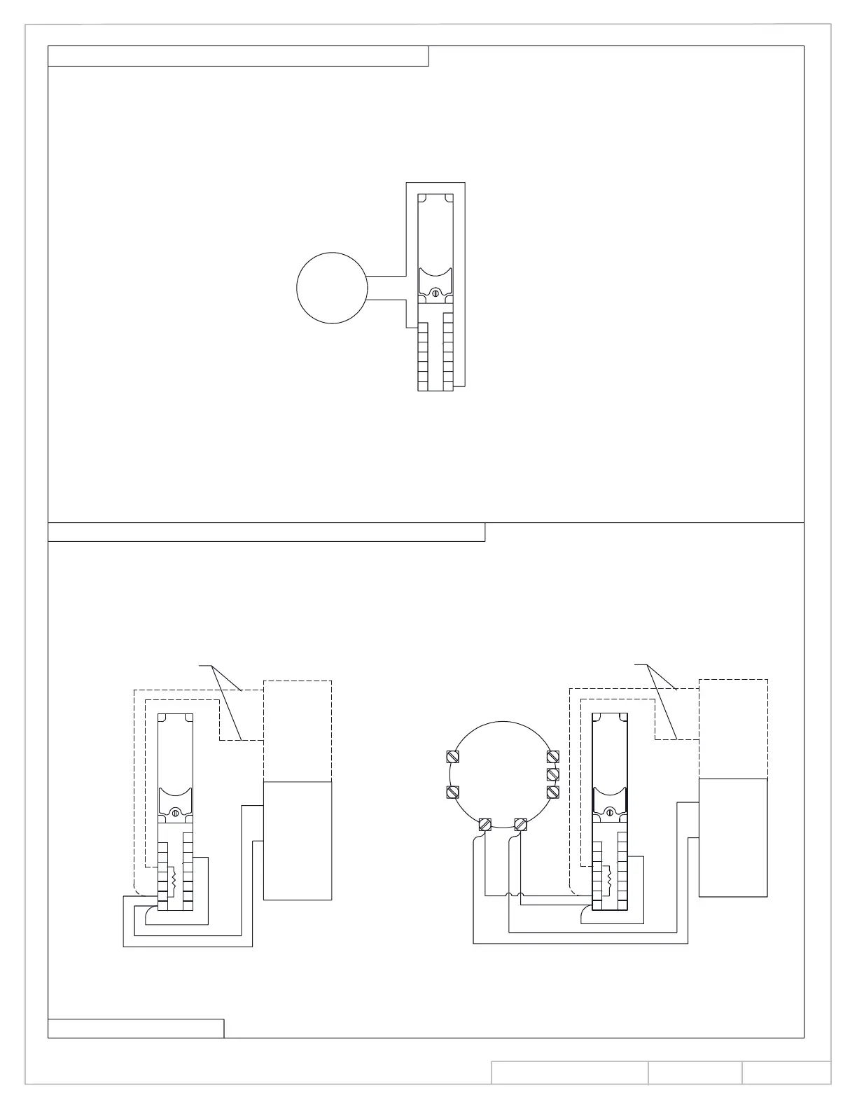
SD-2 DETECTOR TO REMOTE ALARM INDICATOR LAMP
ALARM INITIATION WIRING (4 WIRE CLASS B & 6 WIRE CLASS A)
CONTINUED ON PAGE 11
REMOTE
ALARM
INDICATOR
LAMP
Connect the positive wire of the remote alarm indicator lamp to terminal #8 of the detector module.
Connect the negative terminal of the indicator lamp to terminal #7 of the SD-2 detector.
-
+
*EOL
+
-
*EOL USED IN 4 WIRE APPLICATIONS ONLY
UL/ULC
LISTED
INITIATING
CIRCUIT
CONNECTIONS FOR SIX (6)
WIRE INSTALLATION
RETURN
LOOP
+
-
ALARM RELAY
*EOL USED IN 4 WIRE APPLICATIONS ONLY
REMOTE
DETECTOR
INITIATING
CIRCUIT
UL/ULC
LISTED
1. Make all connections as outlined previously for all units required by the job specifications.
2. Make all signal initiating connections as illustrated in the appropriate figure below. Note wiring differences
for units with remote detectors vs. units without remote detectors. Dashed lines to return loop represent
wires required for six (6) wire applications. These wires are omitted in four (4) wire applications.
3. Connections to only one (1) SD-2 are shown below.
LOOP
RETURN
WIRE INSTALLATION
CONNECTIONS FOR SIX (6)
+
-
*EOL
INS NO.
PAGE
Rev.
08280990
10 of 14
08/13

 Loading...