4
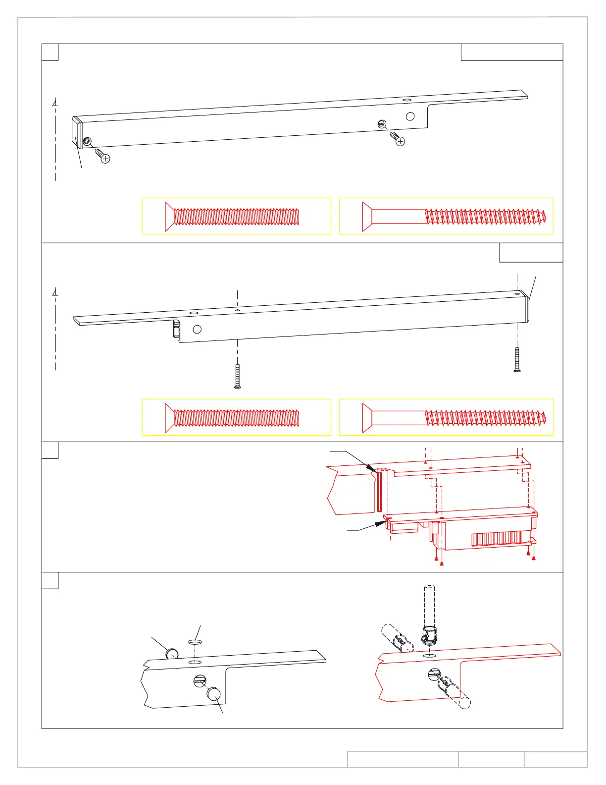
(2) 1/4-20 x 2" metal or (2) No. 14 x 2-3/4" wood screws.
Install with detector cut out toward latch edge of door using
Install track to frame.
8900T and 8900DE
8900PT
END CAP
END CAP
Install with detector cutout toward hinge edge of door using
(2) 1/4-20 x 2" metal or (2) No. 14 x 2-3/4" wood screws.
5
C HINGE
Install detector.
Slide detector slot under standoff
T & DE (RH)
T & DE (LH)
NOTE: NO TOP PLUG
ON PT MOUNTS
Remove (1) wire access plug according to
the installation type.
6
NOTE:
If construction is still being completed near detector installation "DO NOT"
install detector at this time or protect the detector from construction dust
contaminants.
(SURFACE CONDUIT)
C HINGE
NOTE:
Three access wire
holes on optional
surface wired units only.
and attach with (4) screws.
STANDOFF
SLOT
QTY
(2) (2)
QTY
QTY
(2) (2)
QTY
INS NO.
PAGE
Rev.
08280990
2 of 14
08/13