SD-2
15
7
5
14
13
12
11
10
9
1
6
4
3
2
8
SD-2
15
7
5
14
13
12
11
10
9
1
6
4
3
2
8
SD-2
15
7
5
14
13
12
11
10
9
1
6
4
3
2
8
SD-2
15
7
5
14
13
12
11
10
9
1
6
4
3
2
8
SD-2
15
7
5
14
13
12
11
10
9
1
6
4
3
2
8
SD-2
15
7
5
14
13
12
11
10
9
1
6
4
3
2
8
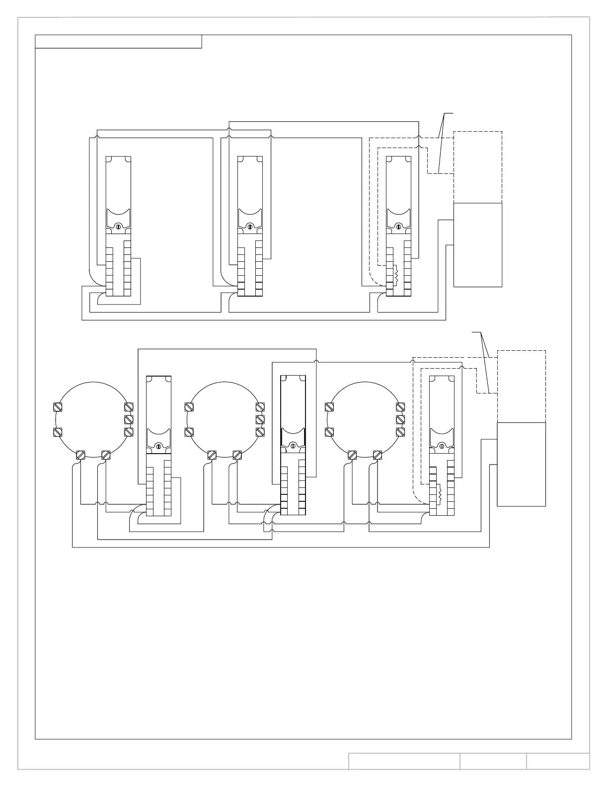
ALARM INITIATION WIRING CON'T.
resistor specified by the fire alarm control panel used. The E.O.L. resistor is only installed in the first
6. In four (4) wire installations, it is the responsiblity of the installer to supply and connect the E.O.L.
WIRE INSTALLATION
CONNECTIONS FOR SIX (6)
as shown for unit 2. The last unit in the run must be connected in the same manner as unit 3.
5. More than three (3) SD-2 detectors are connected by inserting additional units with connections
to detector (3) in the same manner as it is shown connected to detector (2). Detector (2) would
4. Connections for two (2) SD-2 detectors would consist of detector (1) in figure below connected
unit of the run as illustrated.
*EOL USED IN 4 WIRE APPLICATIONS ONLY
*EOL USED IN 4 WIRE APPLICATIONS ONLY
ALARM RELAY
REMOTE
DETECTOR
(3)
(3)
be deleted.
REMOTE
DETECTOR
ALARM RELAY
(2)
DETECTOR
REMOTE
ALARM RELAY
(2)
(1)
*EOL
*EOL
(1)
CIRCUIT
LISTED
UL/ULC
INITIATING
LOOP
RETURN
-
+
+
CONNECTIONS FOR SIX (6)
CIRCUIT
INITIATING
UL/ULC
-
+
LISTED
-
WIRE INSTALLATION
RETURN
+
-
LOOP
INS NO.
PAGE
Rev.
08280990
11 of 14
08/13
 Loading...