SD-2
15
7
5
14
13
12
11
10
9
1
6
4
3
2
8
SD-2
15
7
5
14
13
12
11
10
9
1
6
4
3
2
8
SD-2
15
7
5
14
13
12
11
10
9
1
6
4
3
2
8
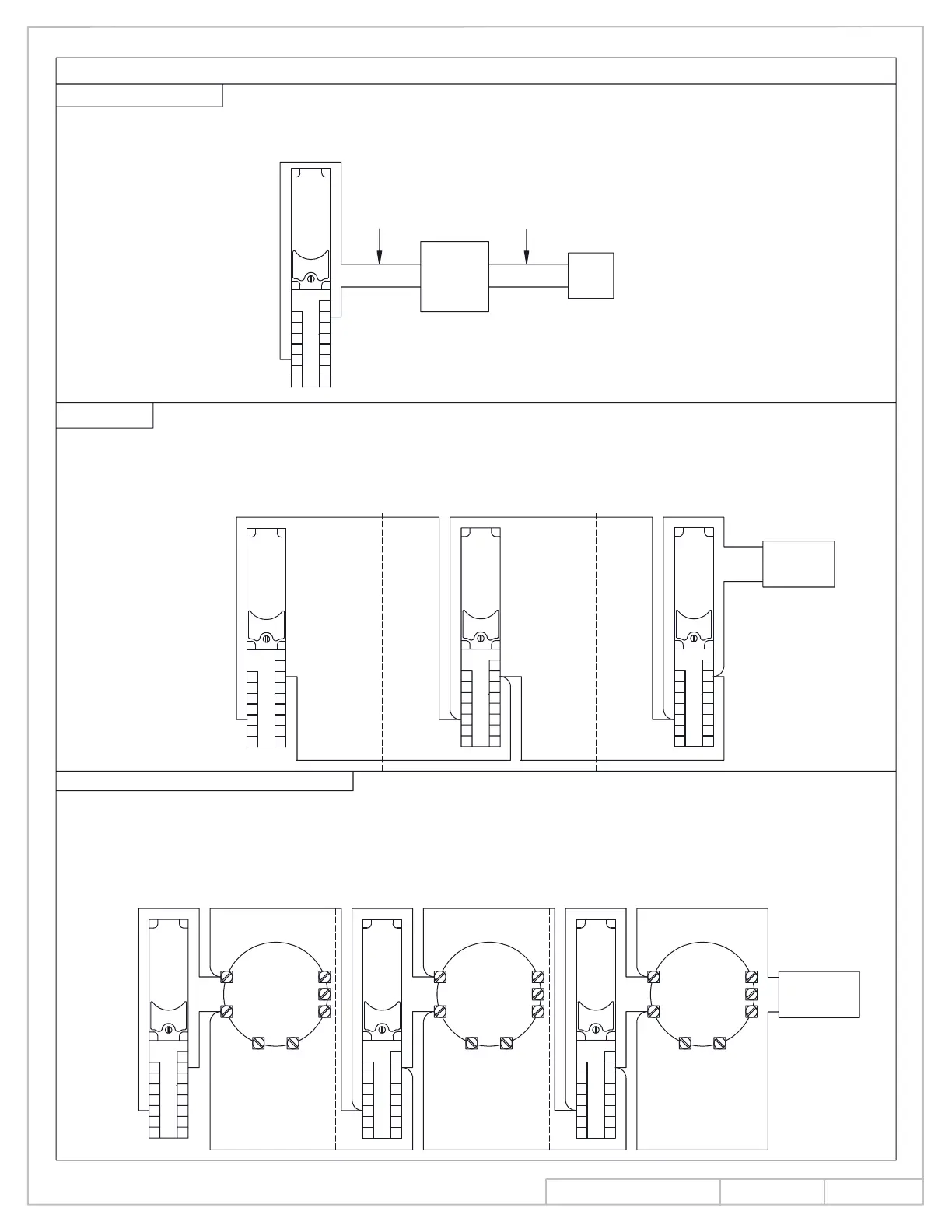
POWER SUPPLY
Insulate all connections. Observe all local codes.
120 VAC, 50/60 HZ
24V AC/DC
24V AC/DC WITH REMOTE DETECTORS
NOTE: FOR ULC INSTALLATIONS, TRANSFORMER
MUST INSTALL IN 4" X 4" ELECTRICAL
BOX X 3" DEEP MINIMUM.
EXTERNAL
(OPTIONAL)
120 VAC, 50/60 HZ: Connect the 120 VAC incoming voltage wires to the primary wires of the transformer.
Connect the secondary transformer wires to terminals #3 and #14 of the detector module.
This connection is not polarity dependent.
PRIMARY
TRANSFORMER
WIRES
STEP
DOWN
TRANSFORMER
120VAC
POWER
INPUT
SECONDARY
TRANSFORMER
WIRES
24V AC/DC NOTE: The step down transformer is not used in this connection. Connect 24V AC/DC
power to terminals #3 and #14 on the detectors. These connections are not polarity dependent.
If the unit is connected to a second unit, connect terminal #3 of the first unit to terminal #3 of the
second unit and connect terminal #14 of the first unit to terminal #14 of the second unit.
Continue this process for any subsequent units to be powered from the same power supply.
24 VAC/DC
POWER SUPPLY
(1)(2)
(3)
+
-
SD-2
15
7
5
14
13
12
11
10
9
1
6
4
3
2
8
SD-2
15
7
5
14
13
12
11
10
9
1
6
4
3
2
8
SD-2
15
7
5
14
13
12
11
10
9
1
6
4
3
2
8
SD-2
15
7
5
14
13
12
11
10
9
1
6
4
3
2
8
-
+
-
+
-
+
+
-
REMOTE
DETECTOR
24VAC/DC
POWER SUPPLY
REMOTE
DETECTOR
REMOTE
DETECTOR
24V AC/DC WITH REMOTE DETECTORS NOTE: The step down transformer is not used in this connection.
Perform wiring connections as illustrated below. Additional units are wired in the same manner as unit #2.
Installations using a combination of SD-2 modules with and without remote area detectors can be
wired accordingly by substituting the wiring diagram section from unit #1, #2, or #3 in step #3 above
instead of unit #1, #2, or #3 below with remote detector. The vertical dashed lines indicate where one
diagram would be exchanged for another.
NOTE: Input voltage must match detector voltage.
(1)(2)
(3)
INS NO.
PAGE
Rev.
08280990
6 of 14
08/13