The following six pages contain wiring options. Wire the units according to building and system
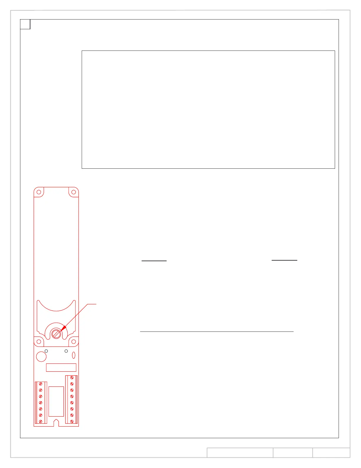
DETECTOR CONNECTION LIST
FUNCTION
AC/DC 24V INPUT
ALARM CONTACTS (NORMALLY OPEN)
ELECTROMAGNET
REMOTE ALARM INDICATOR LAMP +
REMOTE ALARM INDICATOR LAMP -
INTERCONNECT +
INTERCONNECT -
TROUBLE CONTACTS (NORMALLY CLOSED)
24 VDC OUTPUT (UNFILTERED) +
IF JUMPER WIRE J11/J12 IS CUT,
TERMINALS 8, 9 AND 10 ARE
CHANGED TO FORM C RELAY
CONTACTS, RAIL OUTPUT IS
LOST, AND HOLD OPEN ELECTROMAGNETS
MUST BE POWERED FROM A SEPARATE
SOURCE. CONSULT FACTORY
IF REMOTE DETECTORS ARE USED
IN THIS APPLICATION.
TERMINAL
3, 14
1, 2
6, 9
8
7
15
4
5,13
10
N.O. 8
N.C. 9
COM 10
ELECTRICAL SPECIFICATIONS
Voltage input:
Maximum input current:
Maximum output to Remote
Contact ratings:
24 VDC +10% - 15%
24 VAC +10% - 15%
@24 VDC- 161 mA (1 solenoid), 310 mA (2 solenoids)
@24 VAC- 161 mA (1 solenoid), 310 mA (2 solenoids)
300 mA
Alarm and or accessory contacts-
1.25 A at 24 VDC or .3 A at 120 VAC
resistive, maximum.
resistive maximum .
Trouble contacts- 500 mA at 24VDC
12
requirements. Observe all applicable codes.
NOTE: Excludes accessories
NOTE: 120 Volt applications require optional external
transformer.
Alarm Indicator Lamp:
LED & TEST
1
2
3
4
5
6
7
15
14
13
12
11
10
9
8
SD-2
INS NO.
PAGE
Rev.
08280990
5 of 14
08/13