5.6.1 Set for DCW® bus
Address assignment is only required in conjunction
with a SafeRoute system with multi-door application.
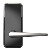
1. Open the door and release the door handle.
‣ The LED is constantly lit up.
2. Turn the key in the unlocking direction until it
stops and hold it there for 10s.
‣ The LED flashes.
3. Turn the key back to its starting position.
4. Press the door handle down repeatedly and check
the operation mode until the LED flashes blue.
5. Turn the key briefly in the unlocking direction until
it stops.
‣ The LED flashes green 1x – 4x:
1x flashing = address 1
2x flashing = address 2 etc.
The signal repeats itself after a pause of 2s.
6. Press the door handle down repeatedly and check
the DCW® address until the desired address is
reached.
7. Turn the key in the unlocking direction until it
stops and hold it there for 10s.
‣ The LED flashes green for 2s and then lights
up constantly blue.
→ The door lock is set for operation on the
DCW® bus.
8. Turn the key back to its starting position.
5.6.2 Set for CAN bus
1. Open the door and release the door handle.
‣ The LED is constantly lit up.
2. Turn the key in the unlocking direction until it
stops and hold it there for 10s.
‣ The LED flashes.
3. Turn the key back to its starting position.
4. Press the door handle down repeatedly and check
the operation mode until the LED flashes yellow.
5. Turn the key briefly in the unlocking direction until
it stops.
‣ The LED flashes green 1x – 4x:
1x flashing = address 1
2x flashing = address 2 etc.
The signal repeats itself after a pause of 2s.
6. Press the door handle down repeatedly and check
the CAN address until the desired address is
reached.
7. If the terminating resistor does not need to be
changed (see chapter 5.2.3), continue with step 9.
8. Turn the key briefly in the unlocking direction until
it stops.
‣ The LED flashes red or green.
The signal repeats itself after a 2s pause.
9. Press the door handle down repeatedly until the
desired terminating resistor function is reached.
‣ LED flashes green or red.
10. Turn the key in the unlocking direction until it
stops and hold it there for 10s.
‣ The LED flashes green for 2s and then lights
up constantly yellow.
→ The door lock is set for operation on the CAN
bus.
11. Turn the key back to its starting position.
5.6.3 Set for Stand Alone operation
1. Open the door and release the door handle.
‣ The LED is constantly lit up.
2. Turn the key in the unlocking direction until it
stops and hold it there for 10s.
‣ The LED flashes.
3. Turn the key back to its starting position.
4. Press the door handle down repeatedly and check
the operation mode until the LED flashes orange.
5. Turn the key in the unlocking direction until it
stops and hold it there for 10s.
‣ The LED flashes green for 2s and then lights
up constantly orange.
→ The door lock is set for Stand Alone operation.
6. Turn the key back to its starting position.
5.6.4 Jump back to the selection
• Jump back from the DCW® address selection to the
operation mode selection:
Turn the key briefly in the unlocking direction until it
stops 1x.
• Jump back from the CAN address selection to the
operation mode selection:
Turn the key briefly in the unlocking direction until it
stops 2x.
5.6.5 Cancel parameterization
• If the changes are not saved within 5 minutes of
the start of parameterization, parameterization is
aborted without the changes being accepted: The
LED lights up red for 2s, then it lights up constantly
in the color for the originally set operation mode.
• If the power supply is interrupted during
parameterization, any unsaved changes are
discarded. Previously saved values are retained.
17SVA door locks 2019-07WN 059743 45532
dormakaba Mounting instructions Parameterization (SVA2000/2000F only)
 Loading...
