Functions (Machine control) - 3
Version 1.36
02/2004
B. Power supply board replacement
This procedure is largely similar to control board replacement.
Please refer for details to that procedure.
In case a fixed water connection is installed start from step 1.
If no fixed water connection is installed, unplug the power cord and proceed with step 6.
1. Close the faucet and remove the external water supply hose. (water inside!)
Pour a cup of hot water.
2. Unplug the power cord.
3. Remove the tank lid.
4. Disconnect the silicon water hose as well as the wiring from the inlet valve.
5. Remove the retaining screw of the tank and lift the tank from the machine. Guide wiring and
hose upright trough the opening in the tank.
6. Remove the right cover.
7. Unplug the connectors from the power supply board. (There is no specific order of disconnecting)
8. Loosen the screws (2) of the retaining rails, remove the rails and take the board out.
9. Install the new board back into the machine and connect the various connectors.
10. Reassemble and test the machine.
C. Operation unit replacement (Foil Print)
In case a fixed water connection is installed start from step 1.
If no fixed water connection is installed, unplug the power cord and proceed with step 6.
1. Close the faucet and remove the external water supply hose. (water inside!)
Pour a cup of hot water.
2. Unplug the power cord.
3. Remove the tank lid.
4. Disconnect the silicon water hose as well as the wiring from the inlet valve.
5. Remove the retaining screw of the tank and lift the tank from the machine. Guide wiring and
hose upright trough the opening in the tank.
6. Remove the water tank, right cover, left cover top cover and rear cover.
7. Remove the operation panel cover.
Be careful not to damage the part when it is being removed.
8. Disconnect the flat cable in the upper left corner of the control board.
Never pull the cable, but release the two retaining clips at each side of the connector.
1
2
3
4
1
2
3
4
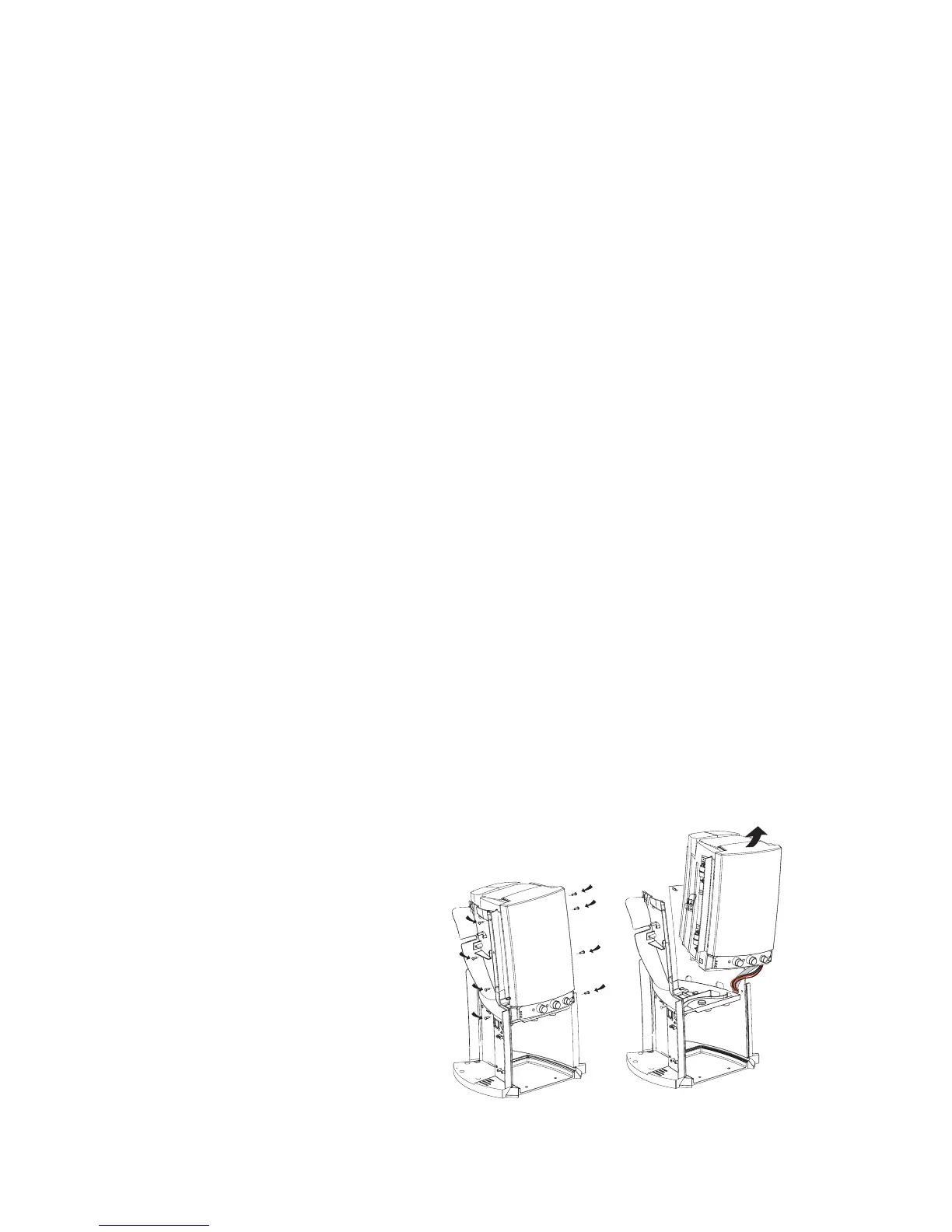
9. Loosen the retaining screws of the
cooling compartment assembly
(4 at each side of the frame and lift
the cooling comparment a little to
create some space for the
flat cable to pass through.