CONTACT US AT www.DRpower.com 9
Specifications
13.3 FPT Premier 10.5 HP Premier
Engine
DR Power Equipment
Refer to your Engine User Manual for
Engine specifications
Briggs & Stratton Powerbuilt
Refer to your Engine User Manual for
Engine specifications
Wheels
Lugged; Sealant filled tubeless Lugged; Sealant filled tubeless
Size
16" X 4.75" 16" X 4.75"
Handlebar Height (adjustable)
High-39.5", Low-35.5" High-39.5", Low-35.5"
Cutting Height
3.5" 3.5"
Cutting Width
26" 26"
Cutting Capacity
4' High Grass, 8' High Weeds and Brush,
2" Dia. Saplings
4' High Grass, 8' High Weeds and Brush,
2" Dia. Saplings
Blade Tip Speed
212 mph (18,660 Ft/Min) 212 mph (18,660 Ft/Min)
Blade Drive
Mechanical; Belt tensioner Mechanical; Belt tensioner
Blade Material
Hardened Steel Hardened Steel
Deck Material
12 GA Welded Steel 12 GA Welded Steel
Frame Material
12 GA Welded Steel 12 GA Welded Steel
Drive
Transaxle – 3 Forward Gears, 1 Reverse
Gear
Transaxle – 3 Forward Gears, 1 Reverse
Gear
Belts
Drive and Blade – V-Belts Drive and Blade – V-Belts
Machine Width, Length, Height
80"L, 29-1/2"W, 46"H 80"L, 29-1/2"W, 46"H
Dry Weight
237 lbs. 223 lbs
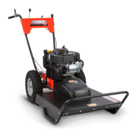
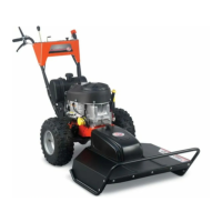
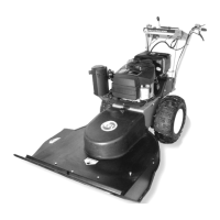
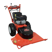
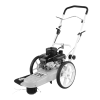
Assembling the DR PREMIER 26" ALL-TERRAIN MOWER
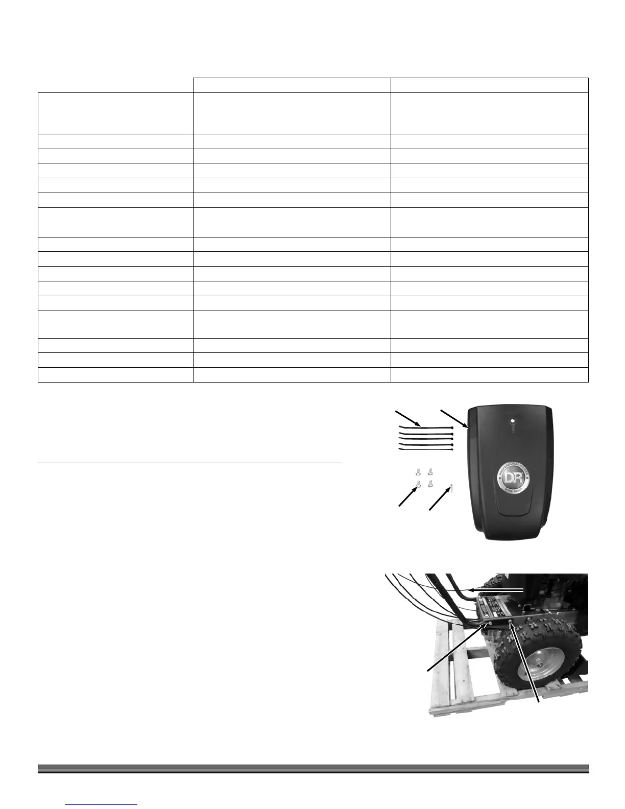
Parts Supplied in Parts Box:
Item Part# Description Qty
1 ......... 11214 ........... Cable Tie, 7-1/2" Long ........................................... 5
2 ......... 37733 ........... Guard, Belt, W/ Labels .......................................... 1
3 ......... 35281 ........... Bolt, Flange, Tri Lobe, 3/8-16 X 3/4, GR5 ZP ....... 4
4 ......... 34407 ........... Bolt, Hex, Flange, 3/8-16 X 1.5", GR5, ZP ............ 1
Compare the contents of the Parts Box with the “Parts Supplied” list above. If
you have any questions please contact us at www.DRpower.com or call 1-800-
DR-OWNER (376-9637) for assistance.
Tools and Supplies Needed:
9/16" Wrench
Wire Cutters
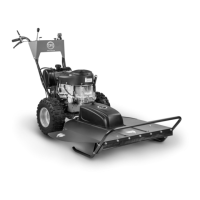
1. With the Handlebars resting on the ground, Align the front holes of the
Handlebars to the front holes in the Frame (Figure 4).
Note: Ensure that the left side cables are outside the Handlebars.
2. Loosely secure the front Handlebar holes to both sides of the Frame with a
3/8-16 X 3/4" Tri-lobe Bolt using a 9/16" Wrench.
3. Rotate the Handlebars up to the desired operator position (there are two
positions to choose from) and install the remaining 3/8-16 X 3/4" Tri-lobe
Bolts. Tighten all four Bolts using a 9/16" Wrench.
Front Bolts
Figure 4
Rear Bolt
Left Side Cables
On Outside Of
Handlebars
Figure 3
4
3
2
1