Dräger Medical AG & Co. KGaA 6173.3
All rights reserved. Copyright reserved.
_ _Printed on_18.05.05_F61733XXT01.fm
39
Function description Babylog 8000
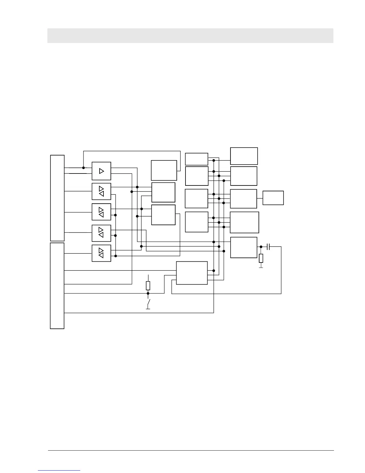
10.3 CPU 68000 PCB
The CPU 68000 PCB comprises the following components: 68000 CPU, EPROM, RAM, time-keeper
RAM, address decoder, multi function peripheral (four 8-bit timers, RS 232 interface, 8-bit I/O port),
DTACK and bus error generator, watchdog, power-on reset, interrupt controller, bus controller, and bus
interface.
The CPU 68000 PCB is clocked with 8 MHz. If the "communication" conversion kit is installed, the clock
frequency is increased to 16 MHz.
Fig. 16: Block diagram of the CPU 68000 PCB
I/O
Digital-Bus 68000
Bus-Interface
Reset
Control-Bus
Adreß-Bus
Daten-Bus
Adreß-Bus
Powerfail
Digital I/O
Status CPU
Optionsschalter
Watchdog
DTACK-,
Bus-Error-
Generator
12 MHz
Co-
prozessor
CPU 68000
16 MHz
8 MHz
Adress-
decoder
EPROM
RAM
Time
Keeper
RAM
Multi
Function
Peripheral
Power-on-
Reset
Interrupt
Controller
Bus-
Controller
Interrupt
Seriell

 Loading...