9023744 - 3rd edition - October 2005
Page 11 of 40
Installing Electrical Connections
Installing Electrical Connections
Connection between Transmitter and Central Unit
Remark:
— The cable gland is suitable for cable diameters from 7 to 12 mm and must only be
used for fixed installations.
— Routing and connecting the electrical installation must only be done by trained
personnel, observing appropriate regulations – use 2-, 3- or multi-core, screened
cable (braided screen, cover ≥80 %).
● Remove the cover of the transmitter.
On the transmitter:
1 Remove two screws from the terminal cover.
2 Remove terminal cover.
● Connect according to the applicable procedure below.
● After having done the electrical connections mount the terminal cover and fix it
with the screws.
● Observe the tightness of the rubber gasket.
● Complete installation by fixing the cover of the transmitter with four screws and
observe tightness.
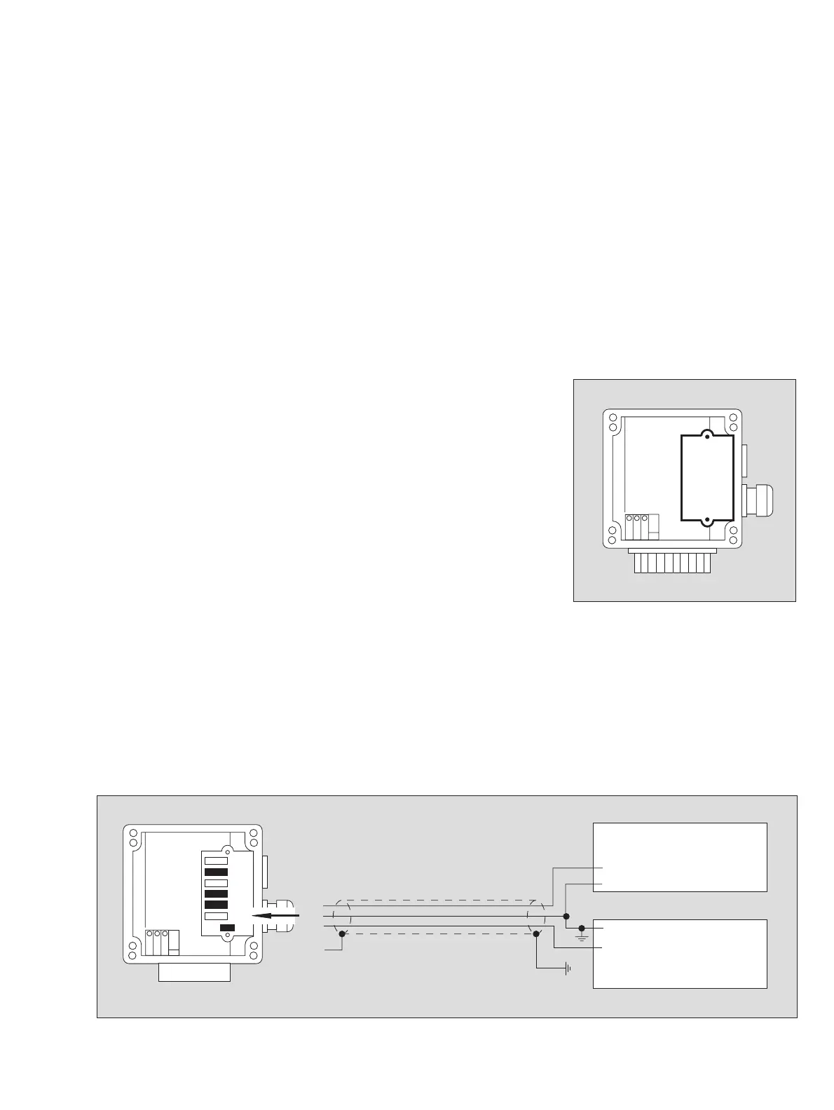
3-Wire Connection
● The cable resistance per core for the connection to the transmitter terminals K1
and K3 must not exceed 20 Ohms.
● The sum total of the input resistance of the central controller and the line resi-
stance of the connection to the transmitter terminal K4 must not exceed
450 Ohms.
● Connect screen to terminal E of the transmitter.
● Ground the transmitter via external terminal, but do not ground screen at the cen-
tral controller,
or
● do not ground transmitter via external terminal, but ground screen in the central
controller.
● Central controller and supply unit can also be combined in one unit.
00723744_1.eps
2
1
1
00823744_1_en.eps
K1
K3
K4
E
0 V
4 to 20 mA
Central controller
K1
K3
K4
E
Supply unit
24 V ±20 %, 0.3 A
+24 V
0 V