Start-Up
Page 18 of 40
9023744 - 3rd edition - October 2005
Check the Measured Value Output
During calibration:
● Compare measured value indicated on the transmitter’s display with the reading
of the corresponding central unit (e.g. channel module Polytron or Regard)
or
● Check alarm triggering by supplying a test gas (concentration somewhat higher
than the alarm threshold) to the Ex-sensor.
Testing the Constantly Amplified Sensor Signal (Sensitivity)
● Perform zero calibration as described under “Calibrating Transmitter Polytron Ex”
resp. “Calibrating Transmitter Polytron Ex R" (page 15 resp. page 16).
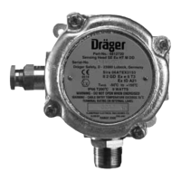
1 Set sliding switch to position »2« = test.
● The measurement signal of the 4 to 20 mA loop oscillates between 2.5 and 5 mA
with approx. 1 Hz, thus preventing alarm triggering.
● The display shows a 3-digit number without a decimal point.
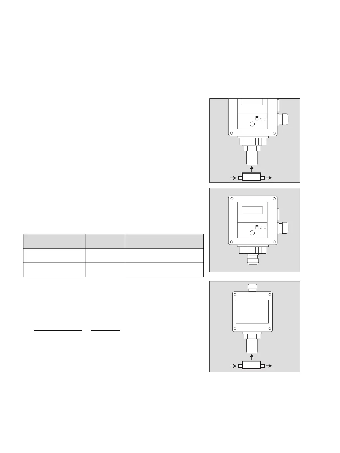
● Depending on the Ex-sensor used supply the recommended calibration gas con-
centration (s. table below) at a flow rate of approx. 0.5 L/min via the calibration
adapter.
— The calibration gas must be a mixture of the gas component to be monitored in
air. Mixtures with nitrogen are not suitable!
Once measured value display has stabilized (after max. 3 minutes):
● Divide the displayed value by the gas concentration (in % LEL) to obtain the sen-
sitivity E:
E =
Displayed value
,
[ 1 ]
gas concentration [ % LEL ]
● Keep sensitivity E for reference purposes when performing repeat measurements
during operation period.
● This test must be performed at regular intervals and following repairs. The results
are to be compared with the result of the measurement performed on start-up.
— If the sensitivity drops below 50 % of the sensitivity on start-up, then the Ex-sensor
is to be replaced.
Ex-sensor resp.
Sensing head
Full scale value Calibration gas concentration
Ex-sensor PR M
Sensing head SE Ex PR M
100 % LEL 10 to 50 % LEL
Ex-sensor LC M
Sensing head SE Ex LC M
10 % LEL 3 to 7 % LEL
02923744_1_en.eps
1
Test gas
03023744_1.eps
1
03123744_1_en.eps
Test gas