PROPRIETARY AND CONFIDENTIAL DRAFT 5 Feb 04
4 - 12
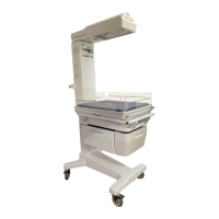
NOTE:
Ensure that the thick end of the wall mount plate is facing
the top of the modified post.
4. Install, but do not tighten, the two #10-32 x 3/8"
screws (J) in the upper holes on the inside of the
modified post.
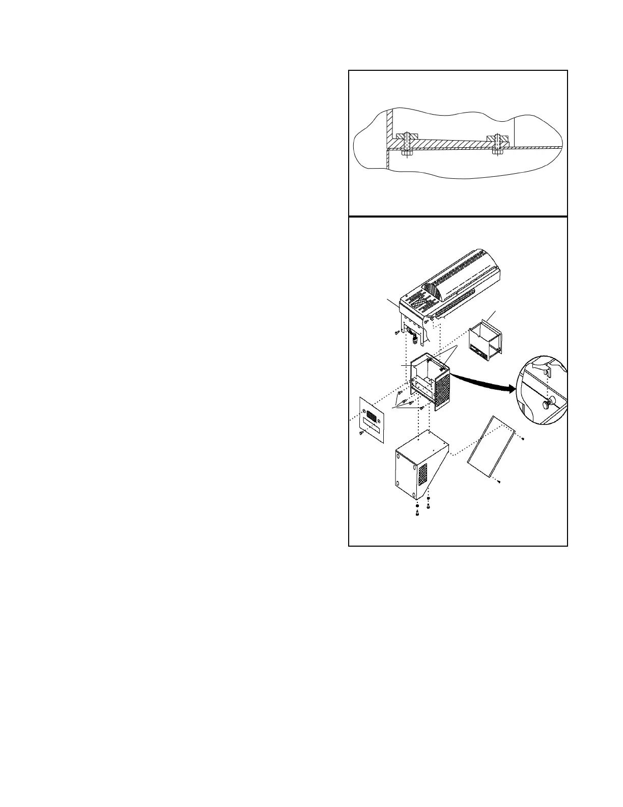
5. Slowly lower the warmer (K) onto the upper post.
Align the slots (L) of the warmer under the two #10-32
x 3/8" screws (J) in the upper holes on the inside of the
modified post.
6. Install the four #10-32 x 3/8" Nylok screws (M) to
secure the pivot bracket (N) to the head support plate
(O).
7. Tighten the two #10-32 x 3/8" Nylok screws (J)
installed in step 4 to secure the warmer to the modified
post.
8. Remove and discard the two #10-32 x 3/8" Nylok
screws (M) from the lower corners of the head support
plate.
9. Thread the warmer power cable (P) out through the
controller opening and connect it to J4 on the power
and control P.C. board assembly.
10. Mount the controller (D) and the back cover (A) on the
modified post (B).
J
K
L
M
N
O
P
J4
D
B
A
L
J