6
3
3
.
.
H
H
a
a
r
r
d
d
w
w
a
a
r
r
e
e
I
I
n
n
s
s
t
t
a
a
l
l
l
l
a
a
t
t
i
i
o
o
n
n
3
3
.
.
1
1
C
C
o
o
n
n
n
n
e
e
c
c
t
t
i
i
n
n
g
g
u
u
p
p
t
t
h
h
e
e
V
V
i
i
g
g
o
o
r
r
R
R
o
o
u
u
t
t
e
e
r
r
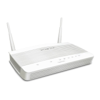
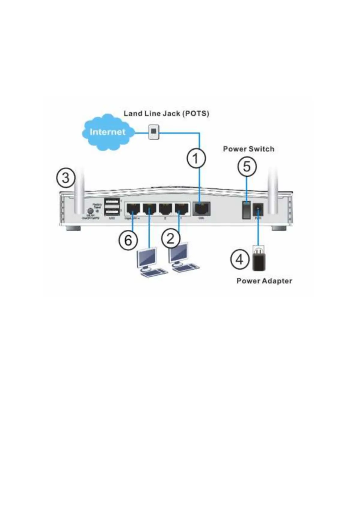
Here we t ake Vigor2765ac as an example.
1. ADSL/ VDSL Connections: Connect t he DSL por t t o t he Modem or DSL por t of t he
ext ernal split t er/ microf ilt er (not supplied) wit h t he RJ-11 line cable. In some
cases, your RJ-11 DSL socket will be built -int o your phone line socket on t he wall
and you won’ t have a separat e microfilt er/ split t er.
2. LAN Connections: Connect a LAN port of t he rout er t o your comput er or sw i t ch.
3. Wireless Antennas: Connect t he wireless ant ennas t o t he rout er
4. Power Supply: Connect t he power adapt er t o t he Vigor 2765’ s PWR socket on
t he rear and plug t he power adapt er int o a suit able mains socket .
Turn t he Vigor 2765 on using it s power swit ch.
5. The rout er will st art up. Aft er complet ing t he syst em t est , t he ACT LED will light
up and st art blinking once per second t o indicat e t hat it is ready for use.
For more det ailed inf ormat ion of LED st at us, please refer t o sect ion 3.1 Front
Panel Overview.
6. Ethernet-based Internet Connections: LAN port P4 can be swit ched t o operat e
as t he Et hernet WAN port . This must be conf igured in t he rout er’ s web int erf ace
bef ore it can operat e in t his mode – Sect ion 5. 3 of t his Quick St art Guide det ails
how t o do t hat .

 Loading...