07-01900G F413-230V AU BD2500 2 Legend Brands Holdings Ltd.
CONTROLS AND OPERATING
INSTRUCTIONS
Set unit upright
NOTICE: Always store, transport, and use the unit in
a horizontal position. If the unit is ever placed in a
vertical position, return it to the horizontal position
and let it stand for at least 30 minutes before turning
it on.
Positioning a Dehumidifier
For best results, operate your dehumidifiers in an en-
closed area. Close all doors and windows that open to
the outside to maximize water removal efficiency. Place
your dehumidifier away from obstructions, and keep it
away from anything that could block airflow into and out
of the unit. For more information about creating an opti-
mum drying environment, contact your local distributor.
Set up drain hose
This unit automatically pumps out water on a regular ba-
sis. This dehumidifier is equipped with a quick-connect
fitting for quick attachment to the provided 12 m drain
hose. Unwrap the entire hose and place the open end in
a sink, drain, bucket or outdoors – anywhere that water
can drain out safely. If you use a bucket or other con-
tainer for water collection, check it regularly to prevent
overflows.
NOTICE: Uncoil and straighten the entire drain hose. Do
not leave any part of the hose coiled and do not place
the end of the hose higher than 6 m above the bottom of
the unit. Also check for kinks or other obstructions that
might restrict the flow of water. Obstructions may cause
a water backup and result in overflows.
Plug in electrical cord
The unit should be plugged into a 230V/50Hz outlet.
Startup display and normal display modes
When unit is first plugged in to AC power, the control
panel display will briefly cycle through a series of
readouts. This is part of the unit’s self-diagnosis proce-
dure and no user intervention is required.
Turn the unit on
The control panel has a display and a touchpad with four
keys. Press the
ON/OFF to turn the unit on. The unit
will now go through a compressor delay countdown (up
to sixty seconds in duration) and a self diagnostics pro-
cess.
Once the compressor delay countdown and self-diag-
nostics are complete, the display will switch to normal
display mode.
UNIT ON XXXX HRS
INLET XXX°C / INLET 00%
The first line of the display shows the total number of
hours the unit has been in operation. This value may be
reset to zero to track job hours (see “Job Hours Reset”
below). The second line of the display alternates be-
tween inlet temperature and inlet humidity.
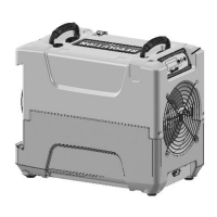
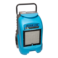
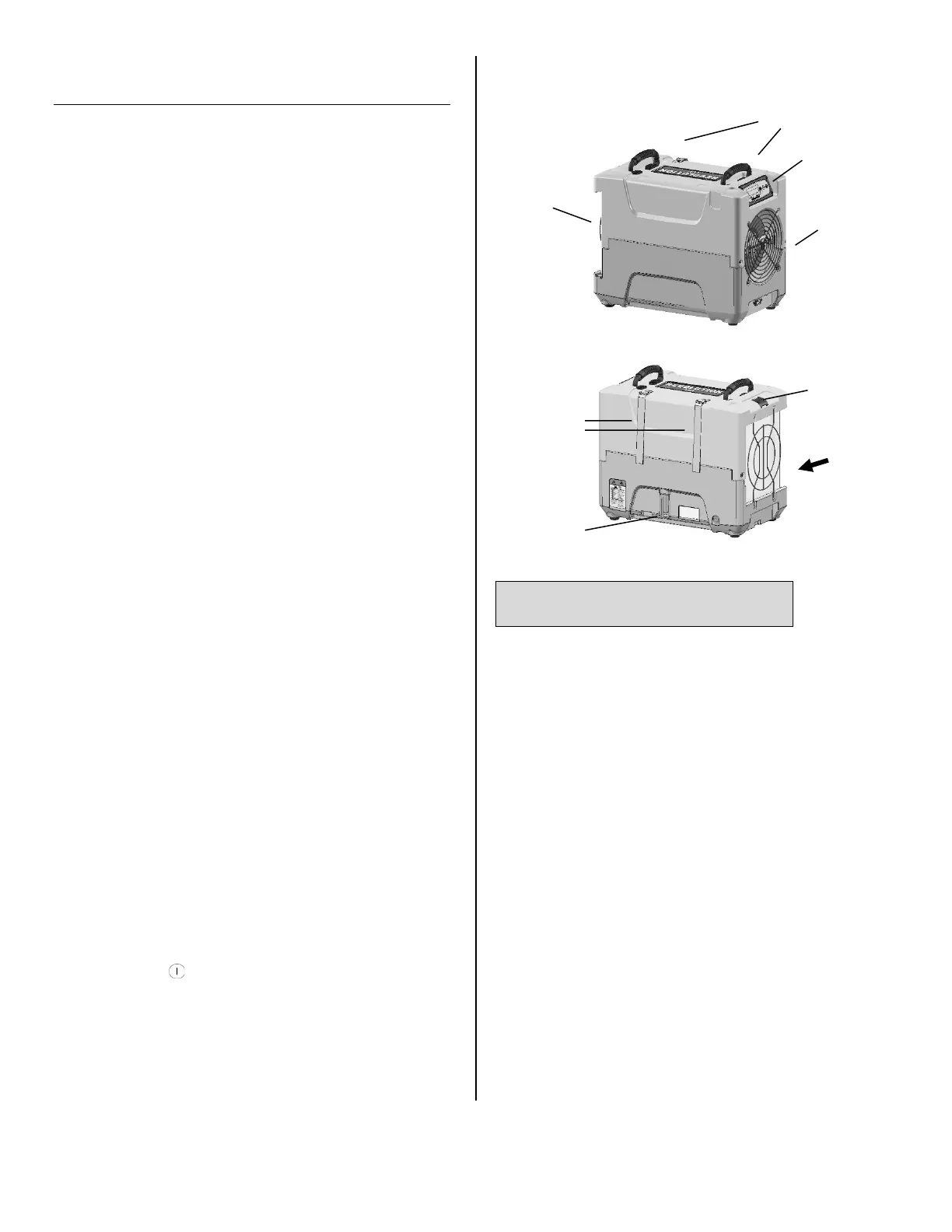
Carry handles
Fig. A: Parts Identification
Condensate
drain quick-
connect
Air inlet
Control
panel
Air outlet
Cord and
hose storage
wraps.
Remove/Insert
air filter here.
Temp/RH
sensor