Owner's Manual
Drivecon Toll Free Ph: 1-800-374-8266
Drivecon reserves the right to alter or amend the above information without notice
Installation
The inverter should be mounted vertically on the wall or on the subpanel of an enclosure.
Enough space shall be reserved around the inverter in order to ensure sufficient cooling, see
diagram below. Also see to that the mounting plane is flat. The inverter shall be fixed with four
screws (or bolts, depending on the unit size).
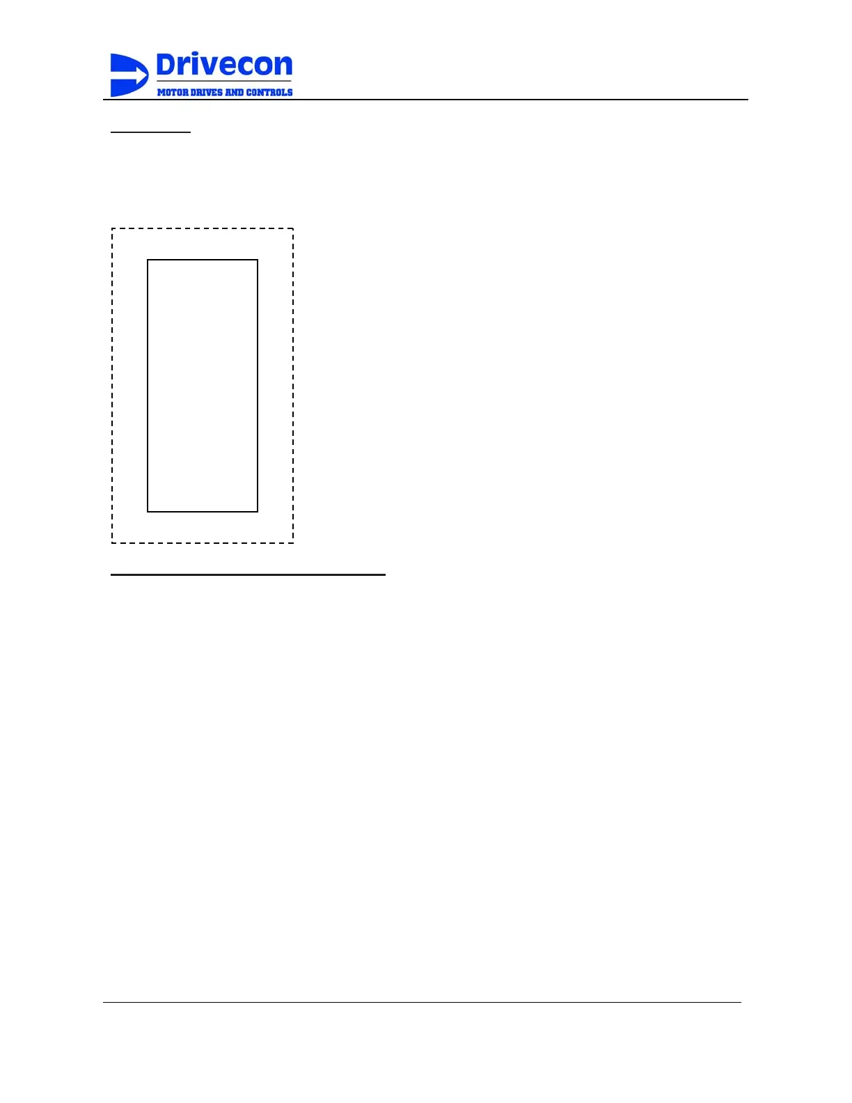
Installation space diagram shown at left. Dotted line represents
perimeter distance around inverter. Refer to Table 3-5, 3-6, and
3-7 for mounting hole dimensions.
Hardware Instructions and Installation
Operating Environment
The installation site of the inverter poses direct impact to the full functionality and life expect-
ancy of your inverter. Please carefully choose an appropriate installation site based on the
following criteria:
• Environment temperature: -10°C to +40°C enclosed without external casing: -10°C to
+55°C chassis mount
• Avoid water dripping or humid environment
• Avoid direct sunlight
• Avoid oily atmospheres
• Avoid corrosive liquid or gas
• Prevent foreign dusts or metal scraps from entering interior
• Keep away from radioactive or flammable material
• Avoid electromagnetic interference (arc welding or power machinery)
• Avoid vibration. If vibration can not be avoided, shock mounts should be installed to
reduce vibration.
• If there are several inverters installed in the same control panel, additional cooling fans
should be installed to lower the environment below 40°C for enclosed units.
• Inverter should be installed facing forward and upright.
• Inverter must be installed as to leave room on all sides for proper heat dissipation. If
installed in an enclosure, the dust cover may be removed for better heat dissipation.
C-4
A
inverter
A
B
C
A