Owner's Manual
Drivecon Toll Free Ph: 1-800-374-8266
Drivecon reserves the right to alter or amend the above information without notice
Chapter B - TECHNICAL DATA
Introduction
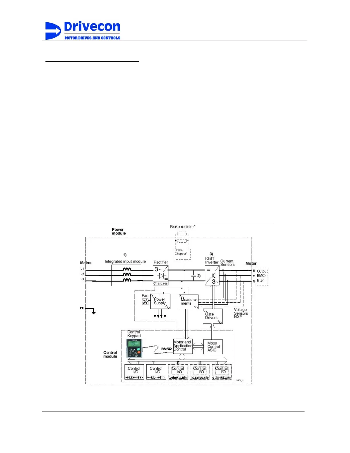
Figure 2-1 represents the block diagram of the inverter. The inverter mechanically
consists of two units, the Power Unit and the Control Unit.
The three-phase AC line inductor (1) at the mains together with the DC bus capacitor (2)
form an LC-filter, which, together with the diode bridge (4) produce the DC-voltage supply
to the IGBT Inverter Bridge (3) block. The AC line inductor also functions as a filter
against High Frequency disturbances from the mains as well as against those caused by
the IGBT inverter to the mains. It improves the form factor of the DC bus input to the
IGBT inverter section. The entire power drawn by the inverter from the mains is active
power. The IGBT Inverter Bridge produces a symmetrical, 3-phase PWM AC-voltage to
the motor.
The Motor and Application Control Block is microprocessor based. The microprocessor
controls the motor based on the information it receives from internal sensors, parameter
settings, control I/O and control keypad. The motor and application control block controls
the motor control ASIC which, in turn, calculates the IGBT switching patterns. Gate driver
circuitry amplifies these signals for driving the IGBT inverter bridge.
Figure B-1
B-1