Owner's Manual
Drivecon Toll Free Ph: 1-800-374-8266
Drivecon reserves the right to alter or amend the above information without notice
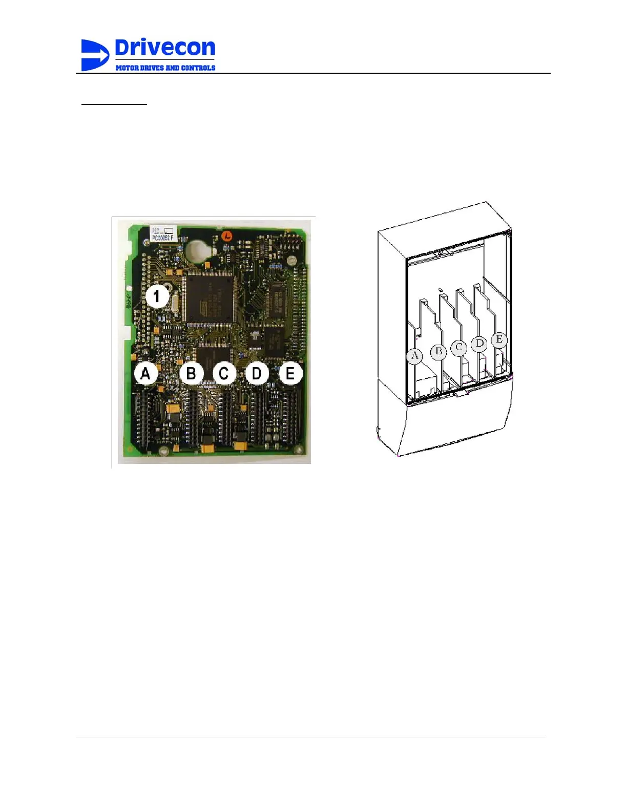
Control unit
The control unit of the inverter consists roughly of the control board and additional boards
(see Figure 4-7a and Figure 4-7b) connected to the five
slot connectors
(A to E) of the
control board. The control board is connected to the power unit through a D-connector (1).
Figure D-7a Figure D-7b
Usually, when the inverter is delivered from the factory, the control unit includes at least
the standard compilation of two basic boards (I/O board and relay board) which are
normally installed in slots A, B, and D. On the next pages you will find the arrangement of
the control I/ O and the relay terminals of the two basic boards, the general wiring diagram
and the control signal descriptions. The I/O boards mounted at the factory are indicated in
the type code.
D-7