10 GSM/GPRS Alarm Communicators
STATUS LEDS
There are 5 LEDs on the PCB (see Figure 4): three green LEDs (L1, L2 and L3), one yellow LED (L4) and one red LED (L5). These
indicate the connection, transmission, malfunction conditions and, for the GS3125 series only, the Communicator status (see table 2).
During initialisation and the programming phase, the LEDs flash.
RED — This LED is normally OFF. It indicates malfunctioning by flashing in the event of trouble. On power-up, this Device will check for
certain trouble conditions to be met in the order listed below. The most significant malfunctioning status will be indicated, with the
corresponding number of flashes of the RED LED (L5), (see below for number of flashes and malfunctioning indication priority).
Indication priority Type of malfunction Red LED flashes
1 (HIGH)
Firmware problem (incorrect firmware) 1
2
Power supply problem 2
3
GSM module problem 3
4
SIM problem 4
5
GSM reception problem 5
6
GPRS problem 6
7
Receiver not available 7
8 (LOW)
Monitoring receiver not detected (receiver 1) 8
No Troubles Off
YELLOW — This LED will switch ON when the interface switches to the GSM Network (due to land line trouble or the lack of this line). If
it flashes slowly, it indicates that a call is taking place on the GSM network (both incoming and outgoing). If lit steadily along with the red
LED, this indicates that the default manufacturer data is loading.
GREEN — The three green LEDs (L1, L2 e L3) indicate the GSM signal strength and status (Table 2), as illustrated in Figure 4:
The first LED (L1) near the fixing hole. If this LED is OFF, the GSM Network service is unavailable (NO SERVICE). If only this LED
is ON, the GSM Network recepetion is weak but sufficient to manage all telephone communications.
The second LED (L2). When this LED is ON, the reception is good. This LED will switch ON only when the first GREEN LED is ON.
The third LED (L3). When this LED is ON, indicates excellent GSM signal strength; it only illuminates when the first and second LEDs
are already ON.
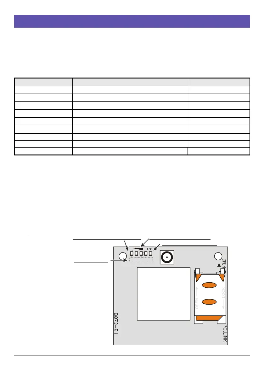
Fig. 4 - Operation indicator LEDs
GSM reception level symbol
Operation indicator LEDs
LEDs Indicating GSM reception
LED numbering
(numbering not present on the
electronic board). This numbering
has only been provided in order
to make identifying each LED
easier within the document.
12345
 Loading...