English
Installation Instructions
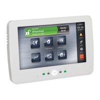
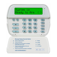
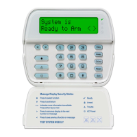
The HS2TCHP keypad can be used on security systems with up to 128 zones. These
keypads are compatible with the Neo PowerSeries HS2016/32/64 and HS2128 panels
V1.0 and higher.
Specifications
l Temperature range: UL/ULC: 0°C to +49°C (32°F to 120°F); EN: -10°C to +55°C
(14°F to 131°F)
l Humidity (MAX): 93%R.H. non-condensing
l Plastic enclosure protection degree: IP30, IK04 (touchscreen excluded)
l Voltage rating: 11.3VDC to 12.5VDC nominal
l Low battery indication: 9VDC
l Connects to control panel via 4-wire Corbus
l Corbus distance: 101 m (332 ft.) (max.); Corbus distance in Extra Power mode: 54
m (177 ft)
l Up to 16 keypads per system
l HS2TCHP current draw (at 12Vdc): 100 mA standby (screen off)/160 mA activated
or alarm (reg. power mode)/230 mA activated or alarm (Extra Power mode). Note:
This does not include 50mA(max) using PGM output.
l Wall mount tamper
l 5 programmable function keys
l Ready (Green LED), Armed (Red LED), Trouble (Yellow LED), AC (Green LED),
HOME (White LED)
l Keypad size: 191 mm x 126 mm x 20.35 mm
l Display area size: 155 mm x 86 mm
l SD card slot: holds any standard Secure Digital (SD) card* (32 x 24 x 2.1 mm). *If
necessary, the SD card can be formatted to file system FAT16 or 32 using a PC.
The maximum size SD card supported is 32GB.
l Wiring: standard four-wire connection
l View angle: horizontal viewing angle: 70° (left)(typ.) 70° (right)(typ.)
l Vertical view angle: 70° (top), 50° (bottom) (typ.)
l Brightness: 280 cd/m2
Unpacking
The keypad package includes the following parts:
l One keypad
l Five mounting screws and five anchors for wall-mounting
l One tamper switch (required for UL commercial burglary listed installations
l Installation instructions and User manual
Mounting
Mount the keypad where it is accessible to designated points of entry and exit. Once a
dry and secure location is selected, do the following:
1.
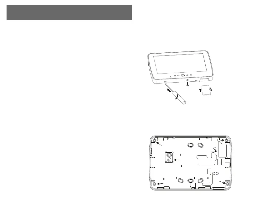
Remove the SD card before opening the touchscreen. See the following figure.
Warning: Do not disassemble the touchscreen without removing the SD card first.
2.
Remove screw at the bottom of the keypad.
3.
Insert screwdriver into slots and pry up to remove.
Figure 1 - Removing the Backplate
S
D
c
a
r
d
gently
push
in
press
to
eject
4.
Secure keypad backplate to the wall using mounting holes. See the following fig-
ure. Use all 4 screws provided unless mounting on a single gang box. Use the
plastic anchors if the unit is to be mounted on drywall. If using the keypad
tamper, secure the tamper plate to the wall with a screw.
Figure 2 - Mounting the Backplate
mounting hole
mounting hole
mounting hole
wiring slot
mounting hole
hole for
tamper
screw