7
Section 5: Standard Installation (Mode 4, TL250 only)
5.1 PC1616/1832/1864, Power864, and Maxsys Panel Setup and
Installation
Refer to the control panel Installation Manuals for detailed installation instructions. Mount the
T-Link on the side wall of the PC4050C or PC4050CR cabinet. Refer to Appendix C for Net-
work Protection installation instructions.
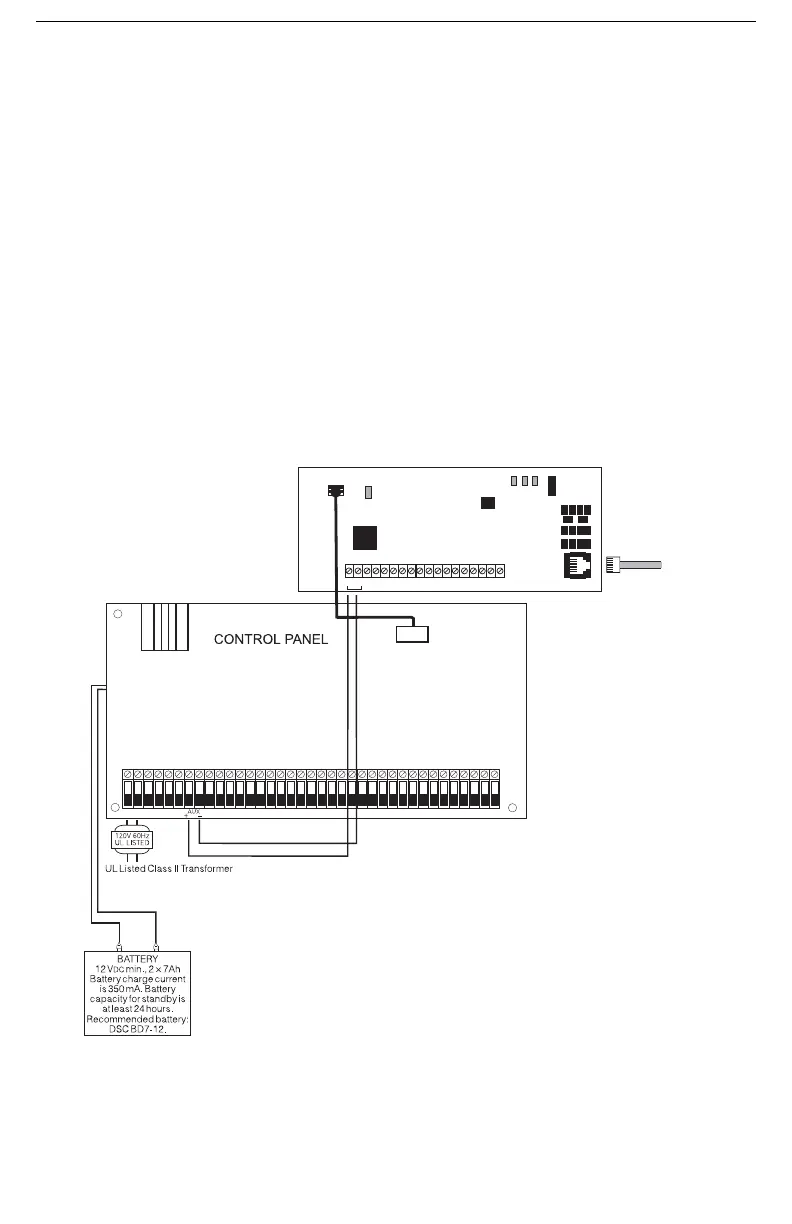
Remove power from the control panel before any connections are made to the T-Link TL250.
Connect the + and - terminals to the panel auxiliary power output. Connect the supplied cable
from the T-Link TL250 white connector to the PC-Link header of the control panel.
The black wire of the PC-Link cable is pin 1 (facing the right side of the board) on the PC-Link
header for the PC5020 v3.2 or higher and PC1616/1832/1864 v4.1 or higher control panels.
The PC-Link header is polarized on the PC4020 v3.31 or higher control panel. Connect the e-
ground to a proper earth-ground connection.
5.2 Standard Connection with PC1616/1832/1864/PC4020(CF)/PC5020(CF)
NOTE: All circuits are supervised and power limited. Refer to section 5.4, UL Listed Commercial Fire Sys-
tems diagram for wire routing. Do NOT route any wiring over the circuit boards. Maintain at least 1”
(25.4mm) separation between circuit board and wiring.
A minimum of 1/4” (7mm) separation must be maintained at all points between non-power lim-
ited wiring and power limited wiring.
12-24Vdc
TX RX GND RED BLK YEL GRN PGM1PGM2 IN1 GND IN2 IN3 GND IN4 EARTH
Network
PC-LINK
PC-LINK
SUPERVISED
SUPERVISED
STAT
Network Connection
Use only CAT5 cable
(300ft / 100m max.)
Supervised
WARNING!: Do not connect transformer
to receptacle controlled by a switch. The
transformer must be UL Listed and have
a restraining means.
V = 12VDC
I = 250mA (275mA with PGM or PC5108)
RED
BLK
+
-
LK
ACT
SPD
16.0V@40VA
NOTE: The black wire is on
the right side and red wire is
on the left.
Recommended: DSC PTD 1640U-CC
DG009338
+
-
NOTE: For ULC Central Station
Fire and Burglary Monitoring con-
figurations please refer to ULC
Installation Sheet part #29002157.

 Loading...