11
Section 7: T-Link TL300 Telephone Simulation (TL300 only)
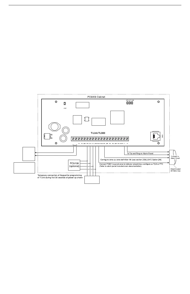
7.1 T-Link TL300 Panel Installation
• Disconnect the AC Power and battery from the Control Panel
• Secure the T-Link TL300 module to the side of the cabinet of the control panel or install the
TL300 in a DSC enclosure (model PC5003C). Refer to Appendix B: T-Link TL300 Compatibil-
ity Chart for a list of panels supported
• Wire the panel's 12V
DC and GND terminals or a unit with a 12VDC 360 mA UL Listed Power
supply to the TL300 (Hardware Revision 05 or higher: 24V 360 mA UL Listed Power Supply
can also be used. Hardware revision is indicated on the PCB and the input terminal will be
labelled + and - and 12-24Vdc will be indicated).
• Wire the panel's Tip and Ring terminals to the T1 and R1 terminals of TL300
• Apply AC and DC to the main control panel. Both the TL300 and the panel should power up
• Program the T-Link TL300 as instructed in section 9.4
7.2 T-Link TL300 Operation
Communication events between the panel, TL300 and the Central Station receiver are as follows:
• When an alarm triggers, the panel goes off-hook.
• The T-Link TL300 module sends a dial tone to the panel.
• The panel dials the telephone number of the central station.
• The T-Link TL300 detects the DTMF dialing and stops sending the dial tone.
• The T-Link TL300 sends a request to the Receiver.
• The Receiver responds with the command to the TL300 to generate the corresponding handshake.
•
After receiving the handshake, the Panel transmits the alarm message in DTMF Contact ID format
.
• The T-Link TL300 decodes and transforms DTMF digits into an IP packet and sends it to the
Receiver over IP.
• The Receiver acknowledges alarm and sends command to the T-Link TL300 to generate a corre-
sponding kiss-off signal.
• After the TL300 generates kiss-off, the panel goes on-hook if no more alarms need to be sent.
NOTE: Do not connect the alarm panel or TL300 to a telephone line.(!)
LCD/PK5500
KEYPAD
12V, 360mA
UL Listed
Power Supply
or Panel Aux
12 VDC
NOTE: For ULC Central Station Fire and Burglary Monitoring
configurations please refer to ULC Installation Sheet part # 29002157.
Hardware Rev. 05
or higher 24V, 360mA
UL Listed Power Supply
can also be used
DG009337
+
-
12-24Vdc

 Loading...