9
Section 6: DVACS Installation (Mode 5, TL250 only)
6.1 DVACS Panel Installation.
Remove power from the control panel before wiring connections to the T-Link TL250 module.
Connect the + and - terminals to the panel auxiliary power output. Connect the DVACS cable
from the T-Link TL250 Adaptor on the PC-Link header to the DVACS connector on the control
panel. Connect the e-ground to a proper earth-ground connection.
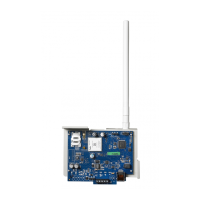
In a typical DVACS Installation, a DVACS panel is connected to an F1/F2 subset that communi-
cates the alarm information to the central station comprising an SG MRL2 receiver with an SG
DVL2A module installed.
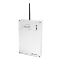
To send DVACS Alarm information over the internet, the T-Link TL250 performs the equivalent
functions of the F1/F2 subset and the polling function of the SG DVL2A. DVACS alarm infor-
mation is sent to the T-Link TL250 by connecting the existing RJ-45 terminated cable to the PC-
Link Header on the TL250 module with an RJ-45 to PC-Link adaptor. The TL250 transmits
DVACS alarm information in the DVACS protocol and T-Link Alarm information in the SIA
protocol over the internet to a System III Receiver with SG-DRL3-IP line card installed.
6.2 DVACS Events
DVACS events generated on DVACS panels connected through the T-Link TL250 follow the
same protocols used on the SG-DVL2A module.
DVACS Alarms Examples
Example 1 (DVACS with receiver set as 1 digit line number)
Printer:
Computer:
Example 2 (DVACS with receiver set as 3 digits line number)
Printer:
Computer:
01 Nov 2004-11:38:22-01/02-SG -01-1-001--Burgl Alm Zn#02
1011 001 A 02
01/02-SG -01-001-014--Burgl Alm Zn#13
101001 014 A 13
DVACS Panel
Installed in Cabinet
ULC Listed Installation
DVACS RS-232
TX, RX, GND
12/24V
DC
Red, Blk
F1/F2
DVACS
Subset
MLR2
with DVL2A
DV1660
DVACS
Network
DVACS
Network
SG-DVL2A
Tx
Rx
ALARM
ACK./
TROUBLE
SELECT
WATCHDOG
WATCHDOG
SELECT
TROUBLE
ACK./
ALARM
Rx
Tx
CARRIERCARRIER
FUNCT. FUNCT.
BACKSPACE
Rx
ESCAPE
TROUBLE
OPTION
ACK.
ENTER
Tx
SG-CPM2
AC
F E D
7 8 9 C
65
0
B
1 2 3 A
4
LAN/WAN/
Internet
LAN/WAN/
Internet
DVACS Panel
Alternate
Power Supply
Installed in Cabinet
ULC Listed Installation
DVACS cable must be run
in metal conduit & terminated
with an RJ-45 connector
RJ-45 to PC-Link Adaptor
12V Red, Blk
DC
T-Link TL250
PC 5003C Cabinet
CON5
CON2
CON1
CON1
CON3
CON3
PCLINKPCLINK
SPD ACT LNK
SPD ACT LNK
STAT
STAT
+12V GND TX RX GND RED BLK YEL GRN PGM1 PGM2 IN1 GND IN2 IN3 GND IN4 EARTH+12V GND TX RX GND RED BLK YEL GRN PGM1 PGM2 IN1 GND IN2 IN3 GND IN4 EARTH
220
System III Receiver
with DRL3-IP Line Card
RRLLL = 02345
IP Account = 010A000034
DVACS Automation Protocol
1 Digit 101A 034...
2 Digits 1010A 034...
3 Digits 10100A 034...
SIA Automation Protocol
1 Digit S025[#000034|...
2 Digits S0245[#000034|...
3 Digits S02345[#000034|...
ID=34
Account = 010A000034
RRLL = 010A
For Decimal Account#
Account = 010A000056
Typical T-Link TL250/DVACS Installation
ULC Listed Power Supply
with Battery Backup
DV1660

 Loading...