8
5.3 Wiring T-Link TL250 to a DSC Compatible Control Panel
• Secure the T-Link TL250 module to the side of the cabinet using the supplied standoffs.
• With AC power removed and the battery disconnected from the DSC control panel, wire the
T-Link TL250 to the panel using 4 wires from the PC-Link of the panel to the ‘PANEL’ con-
nector on the T-Link TL250.
• Wire the panel's AUX+ and - to + and - terminals of the TL250.
• Apply AC and DC to the main control panel. Both the TL250 and panel should power up.
• Program the T-Link TL250 as instructed in Section 9.
NOTE: If a Bell/Siren will not be used, wire the Bell/Siren terminals on the panel with a 1000 ohm resistor.
For Commercial Fire installation, when a bell/siren is used in the application, it should be connected to the
DSC module PC4702BP. Refer to the PC4020CF Installation Manual. The keypad or any other accessory
connected to the Combus shall be connected within 3 feet / 0.9 m and in conduit.
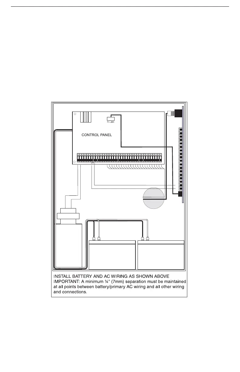
5.4 Battery and AC Power Lead Routing for UL Listed Commercial Fire
Systems
12-24
Vdc
T-Link board must be mounted on the side of the cabinet. Refer to
the mounting instructions in the associated Installation Manual.
+
-

 Loading...