- 14 - 057-042 704 Operating Instructions Issue 2.1 18/06/2007 11:27:00 JR
6 SOLID STATE OUTPUTS
DSE’s utilisation of Solid State Outputs gives many advantages, the main points being:
♦ No Moving Parts
♦ Fully Overload / Short Circuit Protected.
♦ Smaller dimensions hence lighter, thinner and cheaper than conventional relays.
♦ Less power required making them far more reliable.
The main difference from conventional outputs is that solid state outputs switch to negative (–ve)
when active. This type of output is normally used with an automotive or plug in relay.
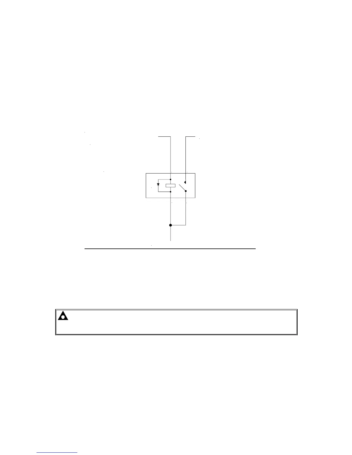
TYPICAL CONNECTIONS
Battery positive (+)
E module
eg. Terminal 3 of 703/4 - FUEL
Fuel Solenoid (+ terminal)
* Observe polarity when using
relays fitted with integral diodes!
*
A
D
B
C
A
B
C
D
Solid State Output
from DSE Module Pin
Automotive
relay Pin
8 Pin Plugin relay Function
3 86 7 Fuel Output
85 2 To Positive supply via fuse
30 1 To Positive supply via fuse
87 3 To Fuel Solenoid
Example of relay pins connected to DSE solid state output to drive a fuel solenoid.
See overleaf for overall typical wiring diagram
NOTE:- The Close Mains Relay should be NORMALLY CLOSED when de-energised for fail
safe reasons. Should the DC supply fail the mains will always be available. The output from the
DSE solid state output when energised will OPEN the relay therefore isolating the mains supply.