057-042 704 Operating Instructions Issue 2.1 18/06/2007 11:27:00 JR - 7 -
2 CONFIGURATION INSTRUCTIONS
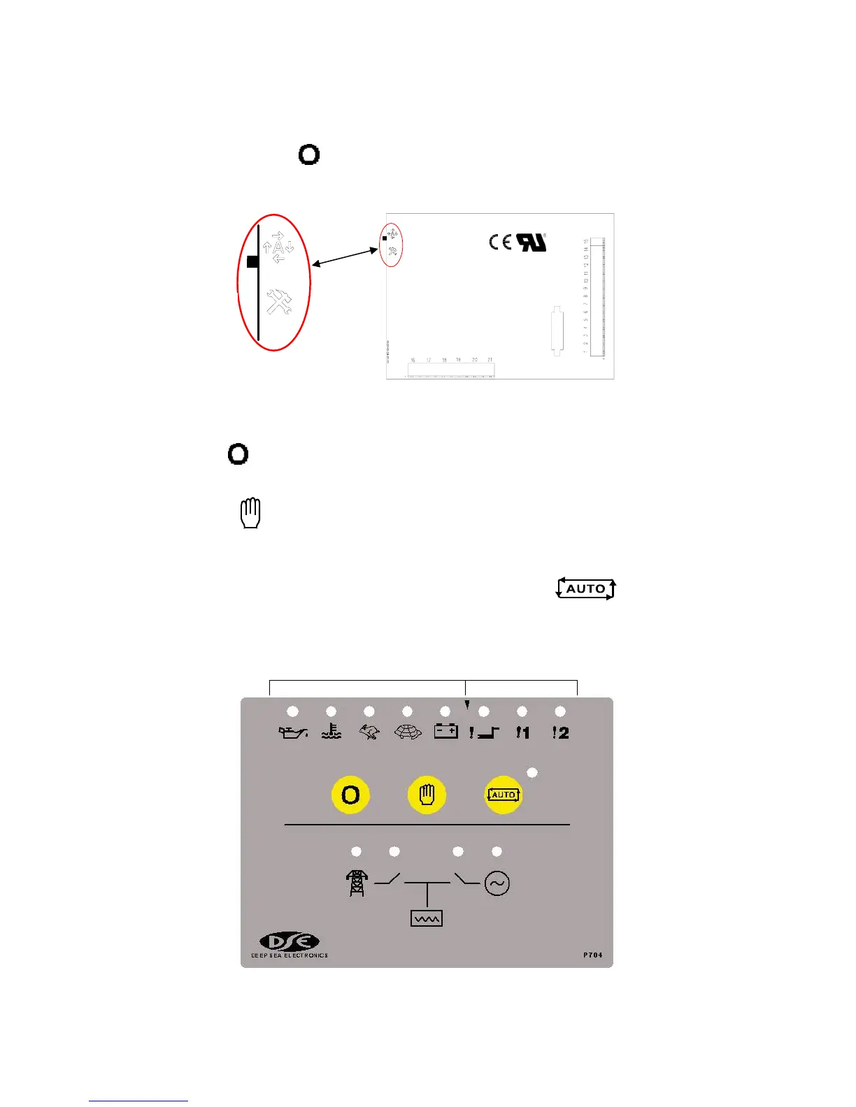
♦ With the unit in Stop mode, Configuration Mode is selected by operation of a small
switch on the rear, left-hand edge of the PCB. This is partially hidden to prevent accidental
operation.
♦ Once Configuration Mode is selected, the ‘Auto’ LED will commence rapid flashing, and all
normal operation is suspended.
♦ The Stop
pushbutton can be used to select the LED ‘code’ that corresponds to the
required function. The 5 left-hand LED’s will form the code. See configuration table over leaf.
♦ The Manual
pushbutton will allow the user to change the associated value. The 3 right-
hand LED’s inform the user of the current setting for the chosen function. See configuration
table over leaf.
♦ When the required parameters are displayed, pressing the Auto
button will save
the new setting, and the process is repeated for each function change.
♦ When configuration is complete, the Configuration Mode Selector Switch should be returned
to the ‘Normal’ position.
Parameter Value
Normal
Configuration