057-042 704 Operating Instructions Issue 2.1 18/06/2007 11:27:00 JR - 15 -
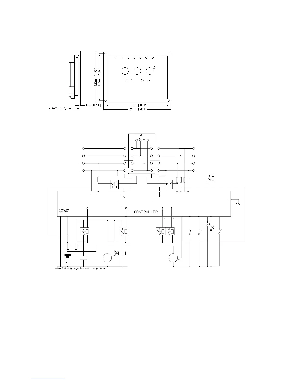
7 DIMENSIONS
Dimensions:
165mm x 125mm x 29mm
(6.5” x 4.9” x 1.2”)
Panel cutout:
149mm x 109mm
(5.9” x 4.3”)
Mounting Method:
4 x 4.2mm diameter holes suitable for M4
screws.
8 TYPICAL CONNECTIONS
F 2A
SSOSSOSSOSSO
SSO = Solid state outputs
= External 'Automotive' or 'Plug-in' type relays
4
1 2
3
5 6 7
2021
Auxiliary Outputs
+
+
8 9 10 11
12
Auxiliary Alarm
Inputs
+
Battery
F2A F
Crank
Fuel
Starter
motor
Charge
alt
+ +
Fuel output
Start output
N
L1
L2
L3
Alternator Output
Load
Mechanical Interlock
N
L1
L2
L3
Mains / Utility supply
14
SSO
Close Gen output
+
G
M
Electrical Interlock
13
SSO
Close mains output
FUSES 2A
Oil Pressure
Engine temperature
Remote Start
Normally closedNormally open
16 17 18 19
Close mains relayClose gen relay
+
*
NOTE
* Close mains relay must be normally closed
to ensure fail safe operation
15
Terminals suitable for 22-16 awg (0.6mm