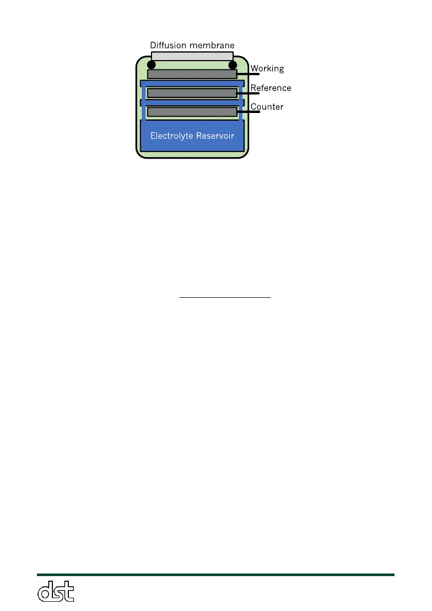
Figure 3. Schematic of electrochemical cell for monitoring gaseous
pollutant concentrations
The electrical currents from the working and reference electrodes
are amplified and converted to a voltage signal for digital acquisition.
Using these two voltage signals, gas concentrations are calculated as
follows:
C
gas
(t) = Gas concentration at time ‘t’ (ppm)
V
working
(t) = Voltage from working electrode at time ‘t’ (V)
V
reference
(t) = Voltage from reference electrode at time ‘t’ (V)
Code = Calibration code (nA/ppm).
Gain = Voltage gain (V/A)
span = Span calibration factor
zero = Zero calibration factor (ppm)
Code is the factory calibration factor, specific to each individual
cell. The code for each cell is logged on the SD card’s Settings file, as
outlined in Section 3.6.1. Gain is gas specific and constant across cells –
it is set in the gas sensing circuitry. Gain is 8x10
5
V/A for all gas species
except for NO
2
and O
3
, where it is equal to 7.3 x10
5
V/A. The span and
zero calibration factors (span and zero, respectively) are determined
experimentally for each cell, as outlined in Section 4. By default, the span
and zero are set to 1 and 0, respectively, and are stored to the SD card.
The NO
2
and O
3
gas cells are identical, except that the NO
2
cell is
outfitted with a chemical filter to remove O
3
from the sample. The O
3
gas
cell has no filter and outputs a signal that is proportional to the
concentration of both O
3
AND NO
2
in the sample. As a result, each O
3
cell