12
RL-61, 61L EN.033 24.01Seibu Giken DST
EN
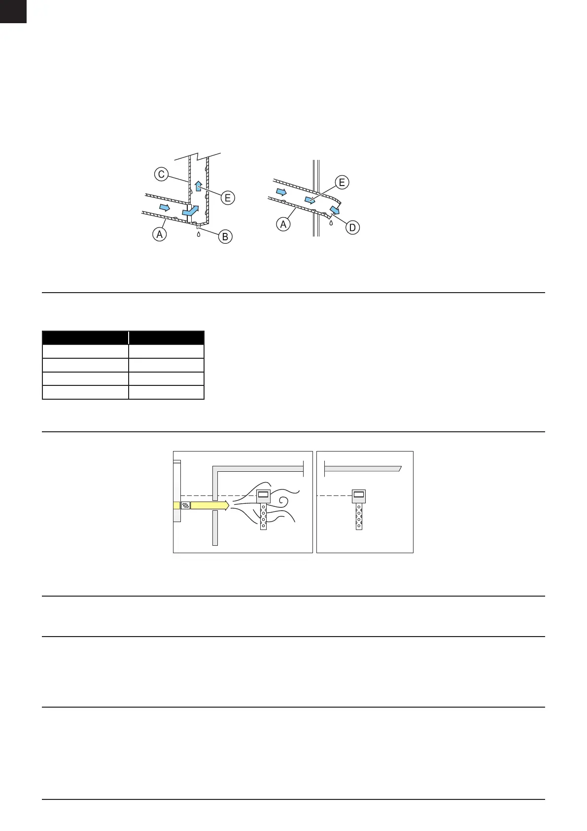
• Install dry air out duct/channel at a high level.
• To maximize the drying capacity, free blowing on dry air out without airow reduction is recommended.
• Allow wet air to disperse freely when exiting the duct.
• It is recommended to insulate the wet air duct.
• The wet air duct must be installed at a sloping outwards angle, due to risk of condensation inside the duct work. The setup will also prevent condensation owing back
into the dehumidier.
• If the duct needs to be installed higher than the wet air outlet, x a condensate drain at the lowest point of the duct.
• Do not connect the air outlet to a ventilation system which can create pressure that will result in reverse airow through the dehumidier.
A. Slope outwards
B. Lowest point
C. Insulation
D. Net
E. Wet air
FIGURE 9: Installation of wet air out duct
4.3 DAMPER INSTALLATION
When installing dampers to adjust the airow to nominal ow, it is recommended to place the dampers according to the table. Installing dampers on the wrong side might result
in humid air mixing with dry air through inltration between the air chambers and aect the capacity. Always maintain a higher pressure on the process air chamber than the
regeneration air chamber by adjusting the dampers. The Delta-P alarm will turn on when the pressure is insucient.
Inlet/Outlet side Install dampers See “9 Troubleshooting” for troubleshooting.
See “7.4 Delta-P Alarm” for function description.
See “11 Technical data” for recommended pressure setting.
Regeneration air inlet ●
Wet air outlet ○
Process air inlet ○
Dry air outlet ●
4.4 HUMIDISTAT/ELECTRONIC CONTROLLER INSTALLATION
Install the humidistat/electronic controller away from the dry air out path to avoid false readings.
FIGURE 10: Humidistat positioning
4.5 ELECTRICAL CONNECTION
Electrical components should be connected to the supply according to the local regulations and requirements.
4.5.1 POWER SUPPLY
The incoming three-phase cable with L1, L2 and L3 are directly connected to the main switch and PE-cable connected to the earth bar.
The electrical feed must be provided on-site in accordance with the electrical diagram and local requirements.
See electrical diagram for a detailed layout and description.
4.5.2 EARTH LEAKAGE CIRCUIT BREAKER
Due to the high capacitive currents present in the AC drive, earth leakage circuit breakers may not function properly.
Note: This is only applicable if the unit is equipped with a frequency converter.