19
RL-61, 61L EN.033 24.01 Seibu Giken DST
EN
8 OPTION & ACCESSORY
8.1 FILTER GUARD
Filter guard is a pressure indicator which tells the condition of the lter. Dierent options are available for purchase and comes in dierent varieties, such as a mechanical
(dierential U-tube manometer) or an electronic lter guard.
FIGURE 14: Electronic lter guard
If the differential pressure increases beyond the
recommended value, the lter needs to be replaced as
soon as possible. This is indicated by warning light or a
message on the PLC.
See “11 Technical data” for recommended pressure for
each lter type.
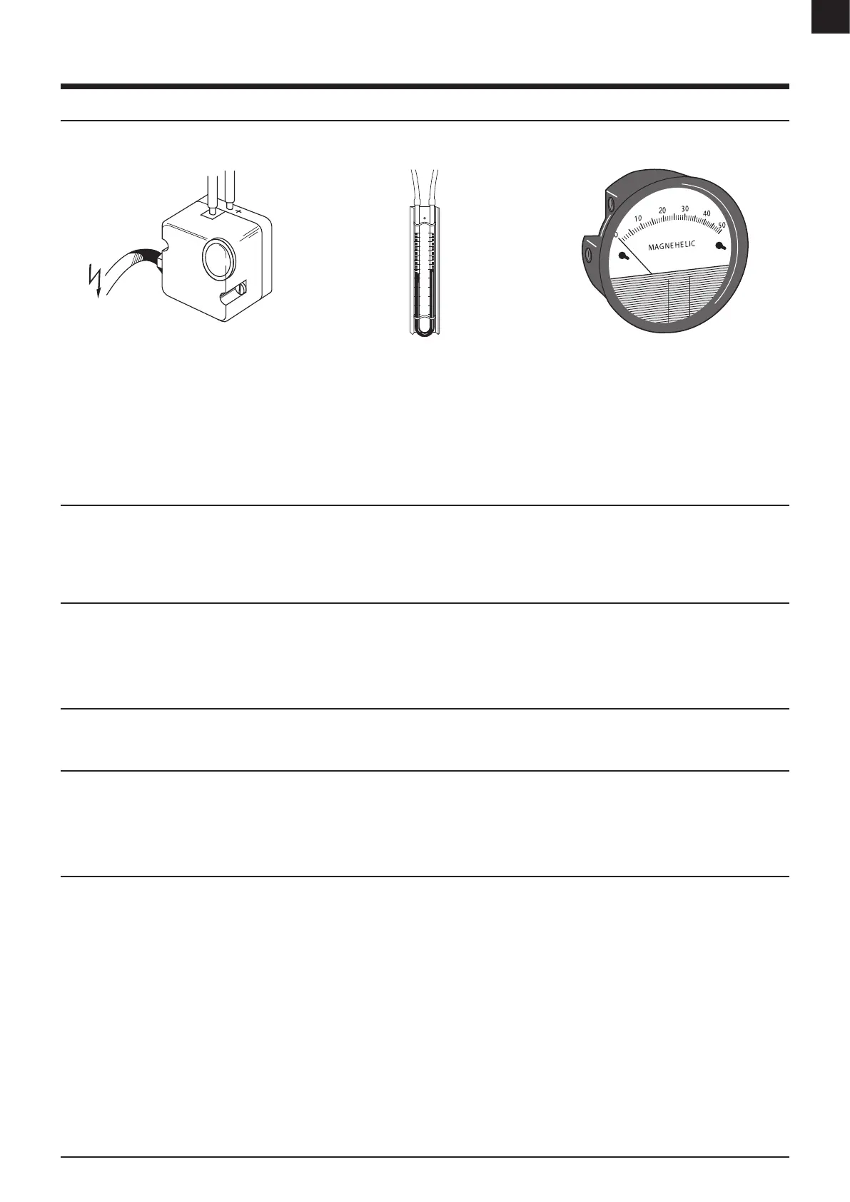
FIGURE 15: Manometer - mechanical lter guard FIGURE 16: Manometer - mekanisk filtervakt
(Magnehelic)
8.2 ROTATION GUARD
A safe guard feature that stops the unit from overheating in case of a sudden stop in the rotor rotation. The rotation guard will stop the unit and turn on an alarm indicator or
display an error message on the PLC.
Note: Included in Energy saving 2 and 3.
8.3 FREQUENCY CONVERTER TO FANS
The frequency converter is used to set the desired airow without dampers and reduce start-up current.
See electrical diagram for more information and location of the frequency converter.
Note: Due to the high capacitive currents present in the AC drive, earth current leakage breaker may not function properly.
8.4 INSULATION
19mm (foamed rubber) insulation can be added along the inside of the process air compartment to prevent possible condensation on the inside and outside surface of the unit.
8.5 ICE-FAN
If an increased airow is needed, the standard process can be replaced and tted with a powerful ICE-fan.
Note: A frequency converter may be required for certain models.
Data ow and other technical data is located in the datasheet.
8.6 ENERGY SAVING
To save energy, the unit can be tted with dierent “Energy saving” features.
Energy saving 1: The reactivation heater power output is regulated in two steps. Using a EH3 T2 or EH4 to adjusts the drying capacity between High, Low & O, as required
to maintain the humidity (or dew point) between two programmable setpoints.
Energy saving 2: The reactivation heater power is fully regulated between zero and full capacity using either binary (multi-step) or linear (triac or actuator) control. Using a
humidity controller EH3 T2 + PLC C2 or an external control signal (BMS + PLC C2), the drying capacity is nely adjusted to accurately maintain the required setpoint (humidity
or dew point).
Contact a DST representative to view the energi saving option for each specic unit as options across the products range may vary.