15
RL-61, 61L EN.033 24.01 Seibu Giken DST
EN
6 OPERATING
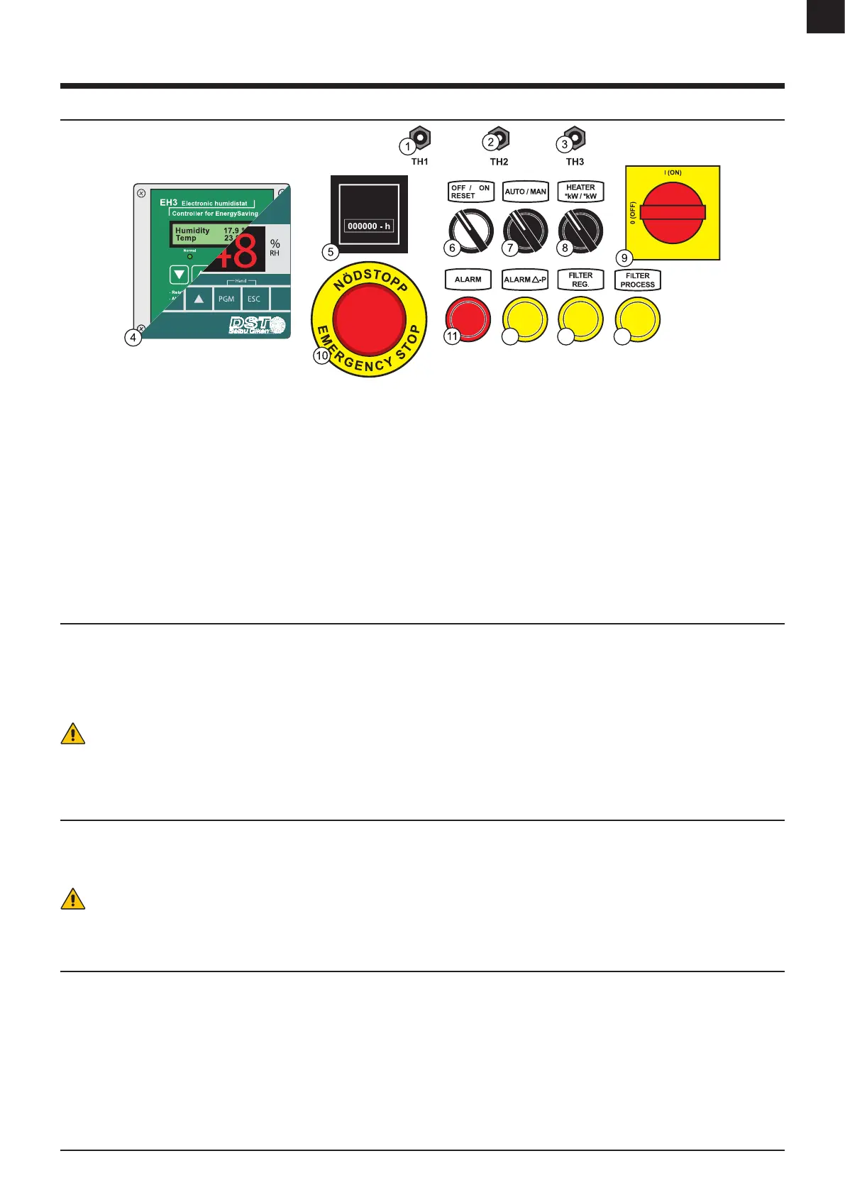
6.1 CONTROL PANEL
12 13 14
1. [TH1] - Safety thermostat for regeneration heater - Reset switch
2. [TH2] - Control thermostat for regeneration heater
3. [TH3] - Safety thermostat for wet air outlet - Reset switch
4. Electronic controller* / Humidistat*
5. Run time meter
6. [OFF RESET/ON] - ON/OFF switch**
7. [AUTO/MAN] - Mode switch for AUTO or MAN
8. [HEATER] - Switch for selecting heater power
9. [MAIN] - Main isolation switch
10. [EMERGENCY] - Emergency stop button
11. [ALARM] - General alarm light
12. [ALARM Δ-P] - Pressure balance alarm light (Unbalanced airow between
regeneration airow and process airow)
13. [FILTER PROCESS] - Warning light for lter guard on process air in*
14. [FILTER REG] - Warning light for lter guard on regeneration air in*
* Option
** The light indicator turns on each time the regeneration heater is active
FIGURE 11: Control panel
Note: Control panel layout - for guidance only. Panel supplied may dier from that shown.
6.2 START
Start the unit.
1. Turn [MAIN]-switch to “I”.
2. Turn [AUTO/MAN]-switch to “MAN” for continuous dehumidication or “AUTO” for automatic-mode with connected humidistat/regulator signal.
3. Select capacity by choose the output on [HEATER] switch.
4. Turn [0/1] to “1” and the unit starts running.
Caution!
When “Automatic restart” selected. The unit starts automatically after a power failure. It is important that all personnel involved with installation, operation, maintenance and
service of the unit are made aware of this function.
6.3 STOP
Unit will shut down.
- A timed cooling down period on the regeneration fan is initiated before turned o.
1. Turn [0/1] to “0”.
Caution!
Do not use the main isolator switch to turn of the unit. Always use the described stop procedure to turn o the unit.
6.4 RESET BUTTONS & SWITCHES
Fuses, overheat protections or motor protectors are found inside the electrical cabinet. The position and denotation of the devices may vary depending on the unit and
conguration.
Reset is only required when a operation is halted by hardware failure or triggered a safety mechanism. See troubleshooting for more information.
See the electrical diagram for correct layout and information of the reset devices.