21
RL-61, 61L EN.033 24.01 Seibu Giken DST
EN
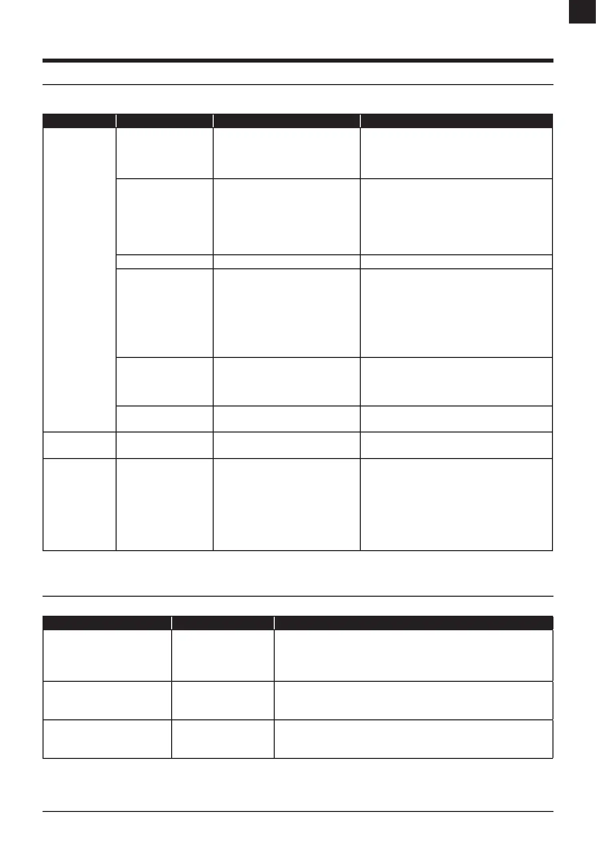
9 TROUBLESHOOTING
9.1 ERROR CODES
The dehumidier will automatically shut down if an error is detected. During shut down, a timed cooling down period on the regeneration fan is initiated before turned o. See
below for error codes.
CODE EXPLANATION CAUSE SOLUTION
If the unit stops and
the ALARM-light is lit.
Process fan overloaded.
Regeneration fan
overloaded.
Excessive airow.
Short-circuit or fan malfunction.
Check fan.
Check setpoint of F1/F2 or Q1/Q2.
Reset F1/Q1 or F2/Q2 – check and adjust airow.
Have a qualied electrical technician to investigate.
Regeneration air thermostat
TH1 has tripped.
Regeneration heater
overloaded.
Note: Not applicable when
tted with steam.
TH1 setting incorrect.
TH1 defective (fail safe).
Incorrect shut down.
Insucient regeneration airow.
Excessive regeneration heater power.
Regeneration heater malfunction.
Check TH1 setting.
Check correct operation of TH1.
Reset TH1 - reset F3 - F5.
Check regeneration airow and fan operation.
Check TH2 setting.
Check and replace heater.
Overload in the transformer. Short-circuit or transformer malfunction. Check transformer.
Wet air thermostat tripped
(TH3).
TH3 setting incorrect.
Excessive regeneration airow.
Excessive regeneration heater power .
Incorrect or intermittent rotor rotation.
Insucient system moisture load.
Check TH3 setting.
Check and adjust regeneration airow.
Check TH2 setting.
Check rotor drive system.
Check process airow and fan operation.
Check process inlet moisture content.
Check RH controller setpoint/output control signal.
Rotation guard sensor has
not detected movement
(KA13).
Rotor drive system failure.
Sensor failure or incorrect clearance.
Check drive motor & transmission (correct belt tension).
Check clearance gap between sensor and rotor marker.
Turn the [0/1]-switch to “0”-position and main switch to “0/
OFF”-position to restore.
Frequency converter alarm.
Note: Option
Frequency converter internal alarm activated Refer to converter manual for fault code explanation.
EMERGENCY
STOP BUTTON is lit.
Operation terminated.
Emergency button activated.
[0/1]-switch is active (if tted with auto restart).
Pull the emergency button to restore.
Turn the [0/1]-switch to “0”-position to restore.
The unit is running
and the ALARM ΔP-
light is lit .
Note: Applicable for
RL-61/71 only.
Internal pressure balance is
not optimal.
The negative pressure on the regeneration air
chamber is insucient. See more information
on “4.3 Damper installation”.
Throttle the damper on regeneration air in or dry air out until
ALARM ΔP-light is turned o.
Reduce the pressure fall by changing the process inlet lter
more frequently.
Check the airow guard.
Check the airow guard setting (recommended is 30Pa).
Note: Top panel must be mounted during testing to avoid
triggering the ALARM ΔP.
FIGURE 20: Troubleshooting table and solution
9.2 GENERAL TROUBLESHOOTING
Check for following if the unit will not start-up.
PROBLEM CAUSE SOLUTION
Unit will not start. None of the light
indicators are on.
No power to unit.
No power to control circuit.
The emergency stop button is
active.
Conrm electric supply and check local isolator is on.
Check remote control is set to ‘On/Run’ position.
Check all circuit breakers are set to ‘Start/On’ position.
Pull the emergency stop button and then turn the operating switch to “0” .
The ALARM-light is on but the unit will
not start.
Alarm circuit is preventing
start-up.
Check TH1 & TH3 thermostats are set.
Check all circuit breakers are set to ‘Start/On’ position.
Check fan motor overloads are set to ‘Start/On’ position.
The dehumidier is turned on but does
not appear to be operating.
A circuit is preventing
operation.
Operation can be checked by lowering control setpoint or switching to ‘manual’ operation.
Check remote control is set to ‘On/Run’ position and if the cable is undamaged.
Conrm electric supply and check local isolator is on.
FIGURE 21: General troubleshooting table and solution