17
RL-61, 61L EN.033 24.01 Seibu Giken DST
EN
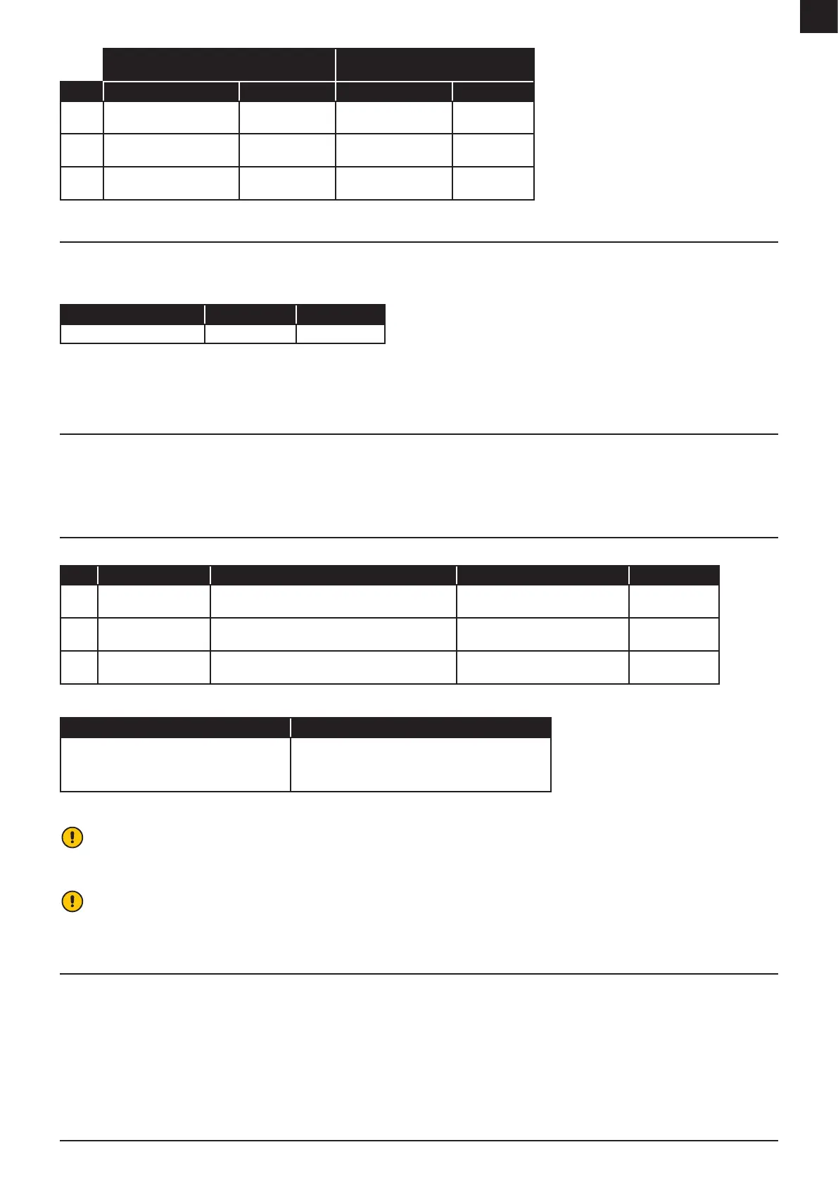
Two-step humidistat
(Applies for electrical heater)
One-step humidistat
(Applies for steam heater)
* See technical data for details on electrical heater
output for reduced power.
See electrical diagram for details and connections.
Mode Humidistat inputs Heater output Humidistat input Heater output
1
Humidistat step 2 (Closed)
Humidistat step 1 (Closed)
Full power Humidistat (Closed) Full power
2
Humidistat step 2 (Opened)
Humidistat step 1 (Closed)
Reduced power* N/A N/A
3
Humidistat step 2 (Opened)
Humidistat step 1 (Opened)
Zero power Humidistat (Opened) Zero power
7.1.4 0-10VDC CONNECTION
Note: Option
This feature replaces the standard built-in humidistat inputs when Energy saving 2 or 3* is tted. A 0-10VDC regulator is used to control the dehumidication capacity on a
precision level when the built-in Humidistat input feature is insucient.
Electronic humidity controller Regulator signal Capacity output
See electrical diagram for customer connection.
EH3 T2/others 0...10VDC 0...100%
* N/A for R-51/60/61, RL-60/61/71.
See “8.6 Energy saving” for more feature description.
7.2 REMOTE CONTROL SWITCH
Connections for a external power switch is available as standard. The remote power switch allows the user to shut down or turn on the unit from another location.
Note: The external power switch overrides the manual and automatic mode and must be restored to start the unit.
See electrical diagram for connections.
7.3 TEMPERATURE SAFETY DEVICES
Integral “fail-safe” temperature devices will protect the unit from damage caused by component failure, incorrect settings or abnormal operating conditions.
Type Thermostat function Thermostat description Thermostat location Reset is required
TH1 Safety thermostat An overheat protection device that stops the unit if the
temperature exceeds the set limit
Inside the regeneration heater
compartment
Yes
TH2 Control thermostat A device that controls the set regeneration temperature Inside the regeneration heater
compartment
No
TH3 Safety thermostat An overheat protection device that stops the unit if the
temperature exceeds the set limit
In the proximity of wet air outlet
Yes
Temperature device types used will vary between models tted with a PLC and those without a PLC. See below.
Units with PLC Units without PLC
*N/A when tted with coils.
See “11 Technical data” for default temperature
settings.
Two shielded electronic sensors, programmed on
PLC as TH2 and TH3. Reset TH3 on PLC.
Mechanical thermostat TH1* – reset on thermostat.
Only mechanical thermostats installed - TH1, TH2 and TH3
Mechanical thermostat TH1* and TH3 - reset on
thermostats.
See electrical diagram for the location of the thermostats.
Attention!
If TH1 or TH3 are tripped, an automatic safe shut down procedure will be initiated. On units tted with a PLC an alarm code will be displayed. On units without a PLC an alarm
is indicated by a red light on the control panel. The shut down procedure includes a timed cooling down period and, if tted, closing of associated valve actuators.
Attention!
Should TH1 trip, it will automatically disable the regeneration heater circuit breakers. These must be reset before attempting to restart the unit.
7.4 DELTA-P ALARM
The separate alarm feature is to ensure there is a sucient negative pressure on regeneration airow chamber compared the pressure in process airow chamber. An alarm
indicator lights up if the pressure is not adjusted. See troubleshooting for more information.
Note: The alarm will not stop the unit.
Note: If pressure is not properly adjusted, humid air from the regeneration airow will inltrate the process airow and mix with the dry air. See “9 Troubleshooting” for solutions.