Printed in Germany / M-MT-BOS
• Edition11.99 • # 231 763
17 … 112
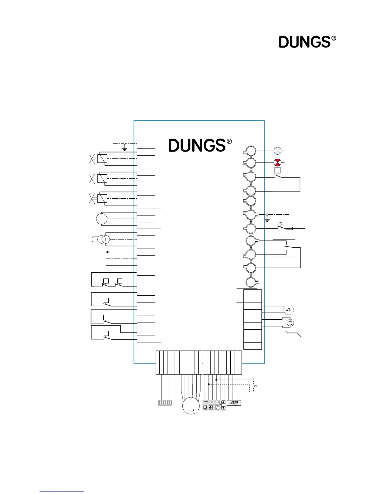
Terminal diagram
Gas firing, pneumatic
modulation
■ Coding plug
Gas firing, pneumatic modula-
tion
Coding plug “gas single-stage” plugged in instead of “servomotor gas”.
Make sure you comply with the burner manufacturer’s specifications.
L1
PE
N
MPA22
B4S3T2
NL1 PET8
T7T6
B5
T1
Feedb. B
Feedb. A
Drive B
Drive A
DGND
+ 24 V
Feedb. B
Feedb. A
Drive B
Drive A
DGND
+ 24 V
M
ϑ
P
M
AIR
ϑ
PE
1
2
3
4
5
6
7
8
9
10
14
15
16
17
11
12
13
18
19
12
Y1
N
3
4
5
Y2
PE
6789
PE
N
Y3
PE
10
N
11
L1
PE
N
121314
L1
PE
15
N
1617
L1
PE
18
N
1920
NC
PE
21
COM
2223
NO
PE
COM
242526
PE
27
NO
COM
NO
COM
28293031
9
+UH
87654321
Pulse
N
UV
ION
LDR
+ 24 V
DGND
DOUT
DIN
DIR
CLK
DGND
RXD
TXD
G 5V
Mains
230 VAC
50 Hz
Valve Y1
LPG
Ignition
transformer
Fan motor
Operation
Fault
L1
PE
N
PE
Valve Y2
Gas-MV1
Valve Y3
Gas-MV2
Pulse counter
UV
Ionisation
F1
S
Display
Encoding
plug, pneu-
matic
Actuator
air flap
Flame failure
controller
(-)
(+)
Output
controller
Control
circuit
eBus
Safety
circuit
Air pressure
switch
GW
min.
GW
VPS
Remonte unlocking device
(only with Dungs display AM01)
P
P
P
+
–
1
2
P
S
i
G
L/A
h
l,m
3