EasyManua.ls Logo

Dungs MPA22 User Manual

Dungs MPA22
112 pages
To Next Page IconTo Next Page
Page #1 background imageLoading...
Page #1 background image
Printed in Germany / M-MT-BOS • Edition11.99 • # 231 763
1 … 112
Read the operating and
mounting instructions be-
fore commissioning.
Only specialised personnel
may perform work on the
automatic burner control system.
Never perform any work
when the control system is
live. This also applies if low-volt-
age components such as servo-
motors, display or communica-
tion components are replaced or
installed.
In case of fuse failure,
check the safety function
of the automatic burner control
system. Otherwise contact weld
caused by short-circuit may oc-
cur.
Only specialised personnel
may set operating param-
eters.
Only use the communica-
tion connection together
with components expressly ap-
proved for this purpose.
Perform the connection re-
lated to the correct phase
and the protective conductor con-
nection according to the terminal
diagram and check it before com-
missioning.
Warranty for the control
system expires on im-
proper handling of the electronic
system or due to incorrect stor-
age.
The data contained in these
instructions specify the au-
tomatic burner control system.
They do not imply any character-
istics.
If you do not follow these
instructions, danger to life
to the equipment may occur.
Technical description
The MPA22 is a microprocessor-con-
trolled, automatic burner control sys-
tem with intermittent duty for control-
ling and monitoring two- and three
stage modulating blower burners with
a single servomotor, electronic modu-
lating blower burners with 2 servomo-
tors in combination with an electronic
control unit, and pneumatic modulat-
ing blower burners with 1 servomotor.
With integrated valve proving system
for operation as automatic gas burner
control system.
Accessories
Flame monitoring device
Servomotors
Display unit
Minimum display
eBUS interface
Mounting bracket
Coding plug
Operating and mounting
instructions
Automatic burner control
system
MPA22
Order data
see Annex
Classification according to EN 298
FMCLJN, depending on programming
FMLLJN, depending on programming
Approvals for gas types
EU type test approval as per EU Gas
Appliance Directive.
MPA22 CE-0085AU316
Approvals for oil types
Register/type test number
MPA22 F185/99

Table of Contents

Other manuals for Dungs MPA22

Question and Answer IconNeed help?

Do you have a question about the Dungs MPA22 and is the answer not in the manual?

Dungs MPA22 Specifications

General IconGeneral
Pressure typeDifferential pressure
Max. operating pressure500 mbar
Electrical connectionScrew terminals
Contact typeSPDT
EnclosurePlastic
Protection ClassIP54
Product typePressure switch
StandardsEN 60529, EN 60730-1, EN 60730-2-6
Storage Temperature-40°C to +85°C

Summary

Operating and Mounting Instructions MPA22

Safety and Handling Precautions

General safety guidelines, warnings, and important notes for safe operation and installation.

Technical Description and Approvals

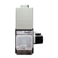
Overview of the MPA22 system features, technical details, and product approvals.

MPA22 Technical Specifications

Electrical and Environmental Specifications

Details on nominal voltage, frequency, performance, ambient conditions, and weight.

Protection, Fuse, and Connection Details

Information on degree of protection, fuse specifications, and protective conductor connection.

MPA22 Component and Specification Details

Breaking Capacities and System Components

Specifications for breaking capacities, flame supervision, servomotors, display, and coding plugs.

Installation and Connectivity Information

Details on communication interfaces, installation position, dimensions, and mounting bracket.

MPA22 Settings and Parameters

Switching Times and Functions

Configuration of switching times and operational functions.

Other Settings and Access Levels

Additional settings, customer parameters, and user access levels.

Servomotor Setpoints and Configuration

Servomotor Characteristics and Gas Firing Setpoints

Setpoints for servomotor characteristics and gas firing modes.

Oil Firing Setpoints

Setpoints for the oil firing, three stage operating mode.

Device Data Logging and Storage

Counters and Storage Devices

Information on device counters, storage devices, and history buffer.

Device Specific Data

Details on device number and production date.

Servomotor Control and Parameterization

Servomotor Direction of Rotation

Configuration options for servomotor rotation direction and reference points.

Parameter Settings for Servomotors

Table detailing parameter settings for servomotor air and gas.

Physical Dimensions and Installation

MPA22 Dimensions and Installation Position

Diagram showing MPA22 dimensions and acceptable installation positions.

MPA22 Operating Modes

Overview of MPA22 Operating Modes

Lists the available operating modes: gas modulating (electronic/pneumatic) and oil firing.

Setting the Operating Mode

Procedure for setting the operating mode using the coding plug.

Gas Firing, Electronic Modulation Mode

Configuration and Functional Sequence

Details on configuration setup and the functional sequence of operation.

Fault Handling in Electronic Gas Firing

Response to Faults and Gas Pressure Monitoring

Describes fault responses, gas pressure switching, and fail-safe programs.

Terminal Diagram: Electronic Gas Firing

Servomotor and Component Connections

Wiring diagram showing connections for servomotors and system components.

Gas Firing, Pneumatic Modulation Mode

Configuration, Sequence, and Faults

Details on configuration, functional sequence, and fault responses.

Gas Pressure and Fail-Safe in Pneumatic Gas Firing

Gas Pressure Switching and Fail-Safe Program

Explanation of gas pressure monitoring and the fail-safe program.

Terminal Diagram: Pneumatic Gas Firing

Coding Plug and Component Connections

Wiring diagram illustrating coding plug use and component connections.

Oil Firing, Three Stage Mode

Configuration and Functional Sequence

Details on configuration setup and the functional sequence of operation.

Fault Handling in Three Stage Oil Firing

Response to Faults

Describes the system's response to various fault conditions.

Terminal Diagram: Three Stage Oil Firing

Coding Plug and Component Connections

Wiring diagram illustrating coding plug use and component connections.

Integrated Valve Proving System

Valve Testing Procedures and Times

Details on valve testing, functional sequence, and test time derivation.

Time Diagram: Electronic Gas Firing

Definitions of Operating States

Defines the various operating states during the burner sequence.

Time Diagram: Electronic Gas Firing Scenarios

Start-up and Operation Fault Scenarios

Illustrates sequences for start-up and flame failure during operation.

Time Diagram: Pneumatic Gas Firing

Definitions of Operating States

Defines the various operating states during the burner sequence.

Time Diagram: Pneumatic Gas Firing Scenarios

Start-up and Operation Fault Scenarios

Illustrates sequences for start-up and flame failure during operation.

Time Diagram: Three Stage Oil Firing

Definitions of Operating States

Defines the various operating states during the burner sequence.

Time Diagram: Three Stage Oil Firing Scenarios

Start-up and Operation Fault Scenarios

Illustrates sequences for start-up and flame failure during operation.

Display and Button Functions

Display Elements Overview

Description of the MPA22 display elements and symbols.

Using the Control Buttons

Explanation of how to use the buttons for control and navigation.

MPA22 Display Modes

Display Mode Categories Overview

Lists the main display modes: Setup, Operating, Information, Parameterization, and Error.

Display Mode Navigation Flowchart

Initial Startup and ID Check Process

Flowchart showing initial startup sequence and ID verification.

Display Mode Navigation Flowchart (Continued)

Accessing Setup and Parameterization Modes

Flowchart detailing access to setup and parameterization modes via password.

Standby Display Indicators

Interpreting Standby Display Messages

Explanation of different messages displayed during standby mode.

Password Entry in Setup and Parameterization

Navigating Parameter/Setup Mode After Password

Flowchart for navigating parameter/setup modes after password entry.

Initial Configuration Process

Basic Configuration Entry Flowchart

Flowchart detailing the process of entering basic configuration.

Setting Motor Start Points

Configuring Air and Gas Motor Start Points

Instructions for setting the start points for air and gas motors.

Commissioning and Setup Mode

Pre-Commissioning Safety Checks

Essential safety checks prior to commissioning the burner system.

Setup Procedure Overview and Access

Guidelines for performing the setup procedure and accessing setup mode.

Setting Main Parameters

Main Parameters for Oil and Gas Firing

Details on setting main parameters for oil and gas firing modes.

Setup Mode: Electronic Gas Firing

Prerequisites and Accessing Setup

Requirements for setup mode and how to access/modify settings.

Setup Mode Flowchart: Electronic Gas Firing

Parameter Entry and Initial Burner Start

Flowchart for entering parameters and initiating the burner start.

Setting Key Parameters: Electronic Gas Firing

Setting Characteristic Points P9, P1, P0

Instructions for setting the main characteristic points P9, P1, and P0.

Setting Ignition Point and Characteristic Curve

Setting Ignition Point P0 and Computing Intermediate Points

Procedure for setting P0 and computing intermediate points P2-P8.

Burner Start and Ignition Point Adjustment

Post-Ignition Procedures and Adjustment

Actions after ignition, including pressure regulator setting and ignition point adjustment.

Setting Characteristic Point P1

Adjusting P1 Value

Instructions for adjusting the P1 characteristic point value.

Setting Characteristic Point P2

Adjusting P2 Value

Instructions for adjusting the P2 characteristic point value.

Setting Characteristic Point P3

Adjusting P3 Value

Instructions for adjusting the P3 characteristic point value.

Setting Characteristic Point P4

Adjusting P4 Value

Instructions for adjusting the P4 characteristic point value.

Setting Characteristic Point P5

Adjusting P5 Value

Instructions for adjusting the P5 characteristic point value.

Setting Characteristic Point P6

Adjusting P6 Value

Instructions for adjusting the P6 characteristic point value.

Setting Characteristic Point P7

Adjusting P7 Value

Instructions for adjusting the P7 characteristic point value.

Setting Characteristic Point P8

Adjusting P8 Value

Instructions for adjusting the P8 characteristic point value.

Setting Final Characteristic Points and Burner Load

Setting Characteristic Point P9

Instructions for setting the P9 characteristic point and burner load range.

Setting Minimum and Maximum Burner Load

Setting the minimum (Pmin) and maximum (Pmax) burner load values.

Setup Mode: Pneumatic Gas Firing

Prerequisites and Accessing Setup

Requirements for setup mode and how to access/modify settings.

Setup Mode Flowchart: Pneumatic Gas Firing

Parameter Entry and Initial Burner Start

Flowchart for entering parameters and initiating the burner start.

Setting Working Points: Pneumatic Gas Firing

Setting Working Points P9, P1, P0

Instructions for setting the working points P9, P1, and P0.

Burner Start and Ignition Point Adjustment

Post-Ignition Procedures and Adjustment

Actions after ignition, including pressure regulator setting and ignition point adjustment.

Exiting Setup Mode: Pneumatic Gas Firing

Finalizing Setup and Exiting

Procedure for finalizing setup and exiting the mode.

Setup Mode: Three Stage Oil Firing

Prerequisites and Accessing Setup

Requirements for setup mode and how to access/modify settings.

Setup Mode Flowchart: Three Stage Oil Firing

Parameter Entry and Initial Burner Start

Flowchart for entering parameters and initiating the burner start.

Setting Working Points: Three Stage Oil Firing

Setting Working Points P9, P3, P1

Instructions for setting working points P9, P3, and P1 for oil firing.

Setting Ignition and Changeover Points

Setting Ignition Point P0

Instructions for setting the ignition point P0.

Setting Changeover Points P2, P4

Instructions for setting changeover points P2 and P4.

Burner Start and Ignition Point Adjustment

Post-Ignition Procedures and Adjustment

Actions after ignition, including pressure regulator setting and ignition point adjustment.

Setting Working Points P1 and P3

Setting Working Point P1 (Stage 1)

Instructions for setting the working point P1 for stage 1.

Setting Working Point P3 (Stage 2)

Instructions for setting the working point P3 for stage 2.

Setting Working Points P3 and P9

Setting Working Point P3 (Stage 2)

Instructions for setting the working point P3 for stage 2.

Setting Working Point P9 (Stage 3)

Instructions for setting the working point P9 for stage 3.

Setting Changeover Points P2 and P4

Setting Changeover Point P2

Instructions for setting the changeover point P2 between stages.

Setting Changeover Point P4

Instructions for setting the changeover point P4 between stages.

Operating Mode Display: Gas Firing

Electronic and Pneumatic Modulation Displays

Displays used in operating mode for electronic and pneumatic gas firing.

Operating Mode Flowchart: Electronic Gas Firing

Initial Startup and Internal Tests

Flowchart showing initial startup sequence and internal system tests.

Operating Mode Flowchart: Electronic Gas Firing (Continued)

Safety Chain and Air Servo Drive Check

Checks for safety chain and air servo drive idle position.

Operating Mode Flowchart: Electronic Gas Firing (Continued)

Ignition and Pre-Ignition Sequence

Flowchart detailing the ignition and pre-ignition sequence.

Operating Mode Flowchart: Electronic Gas Firing (Continued)

Valve Test Phases

Flowchart illustrating the different phases of the valve test.

Operating Mode Flowchart: Electronic Gas Firing (Continued)

Post-Venting and Standby States

Flowchart showing post-venting and transition to standby states.

Operating Mode Display: Three Stage Oil Firing

Overview of Oil Firing Display

Description of the display elements in operating mode for oil firing.

Operating Mode Flowchart: Three Stage Oil Firing

Initial Startup and Internal Tests

Flowchart showing initial startup sequence and internal system tests.

Operating Mode Flowchart: Three Stage Oil Firing (Continued)

Pre-Vent and Watchdog Checks

Flowchart detailing pre-vent sequence and watchdog checks.

Operating Mode Flowchart: Three Stage Oil Firing (Continued)

Ignition and Stabilization Sequence

Flowchart illustrating the ignition and stabilization sequence.

Operating Mode Flowchart: Three Stage Oil Firing (Continued)

Stage Transition and Operation

Flowchart showing stage transitions and operational states.

Operating Mode Flowchart: Three Stage Oil Firing (Continued)

Post-Venting and Standby States

Flowchart showing post-venting and transition to standby states.

Information Mode Overview

Available Information Categories

Lists categories of information available: counts and system data.

Information Mode Navigation

Viewing Fuel Consumption and Operating Hours

Flowchart for viewing fuel consumption and operating hours.

Information Mode Navigation (Continued)

Viewing Stage Operating Hours and Start Counts

Flowchart for viewing stage operating hours and start counts.

Information Mode Navigation (Continued)

Viewing Software and Controller Information

Flowchart for viewing software version, serial number, and production date.

Service Mode: Electronic Gas Firing

Accessing Service Mode and Data Displayed

How to access service mode and a list of displayed data.

Service Mode Navigation: Electronic Gas Firing

Viewing Ignition Point P0 and Characteristic P1

Flowchart for viewing P0 ignition point and P1 characteristic point values.

Service Mode Navigation: Electronic Gas Firing (Continued)

Viewing Characteristic Points P2 to P5

Flowchart for viewing characteristic points P2, P3, P4, and P5.

Service Mode Navigation: Electronic Gas Firing (Continued)

Viewing Characteristic Points P6 to P9

Flowchart for viewing characteristic points P6, P7, P8, and P9.

Service Mode: Error Code Display

Viewing Recent Error Codes

Flowchart for viewing the most recent error codes.

Service Mode: Error Code Display (Continued)

Viewing Subsequent Error Codes

Flowchart for viewing subsequent error codes.

Service Mode: Test Times and System Information

Viewing Valve Test Times and Flame Quality

Flowchart for viewing valve test times and flame quality indication.

Viewing eBUS Address

Flowchart for viewing the eBUS address.

Service Mode: System Status and Address

Viewing Mode Indicator and Modulation Limits

Flowchart for viewing mode indicator and modulation limits.

Viewing Controller Address

Flowchart for viewing the controller address.

Service Mode: Pneumatic Gas Firing

Accessing Service Mode and Data Displayed

How to access service mode and list of data displayed.

Service Mode Navigation: Pneumatic Gas Firing

Viewing Ignition Point P0 and Characteristic Points P1, P9

Flowchart for viewing P0 ignition point and P1, P9 characteristic points.

Service Mode: Error Code Display

Viewing Recent Error Codes

Flowchart for viewing the most recent error codes.

Service Mode: Error Codes and Test Times

Viewing Subsequent Error Codes

Flowchart for viewing subsequent error codes.

Viewing Valve Test Times

Flowchart for viewing valve test times.

Service Mode: System Status and Address

Viewing Flame Quality and eBUS Address

Flowchart for viewing flame quality and eBUS address.

Viewing Mode Indicator and Controller Address

Flowchart for viewing mode indicator and controller address.

Service Mode: Three Stage Oil Firing

Accessing Service Mode and Data Displayed

How to access service mode and list of data displayed.

Service Mode Navigation: Three Stage Oil Firing

Viewing Ignition Point P0 and Working Point P1

Flowchart for viewing P0 ignition point and P1 working point values.

Service Mode: Working Points and Error Codes

Viewing Working Points P3 and P9

Flowchart for viewing working points P3 and P9.

Viewing Recent Error Codes

Flowchart for viewing the most recent error codes.

Service Mode: Error Code Display (Continued)

Viewing Subsequent Error Codes

Flowchart for viewing subsequent error codes.

Service Mode: System Status and Address

Viewing Flame Quality

Flowchart for viewing flame quality indication.

Viewing eBUS Address

Flowchart for viewing the eBUS address.

Service Mode: Controller Status and Address

Viewing Status Indicator

Flowchart for viewing the status indicator.

Viewing Controller Address

Flowchart for viewing the controller address.

Parameterization Mode Overview

Accessing Parameterization Mode

Instructions on how to access parameterization mode from standby.

Parameterization Mode Entry

Password Entry for Parameterization

Flowchart detailing the password entry process for parameterization.

Parameterization: eBUS Address and Run-on Time

Setting eBUS Communication Address

Instructions for setting the eBUS communication address.

Setting Run-on Time

Instructions for setting the run-on time parameter.

Parameterization: Wait Time and Pulse Divider

Setting Wait Time in Minutes

Instructions for setting the wait time in minutes.

Setting Pulse Divider

Instructions for setting the pulse divider for fuel quantity measurement.

Parameterization: Air-Flow Control and Error Memory

Setting Air-Flow Control Flap Position

Instructions for setting the air-flow control flap position in standby.

Clearing Error Memory

Procedure for clearing the error memory.

Parameterization: Valve Test System and Y2 Test Time

Setting Valve Test System Switch Position

Instructions for setting the valve test system switch position.

Setting Test Time for Valve Y2

Instructions for setting the test time for valve Y2.

Parameterization: Valve Y3 Test Time and Monitor Function

Setting Test Time for Valve Y3

Instructions for setting the test time for valve Y3.

Setting Monitor Function Switch Position

Instructions for setting the monitor function switch position.

Parameterization: Control Address

Setting System Control Address

Instructions for setting the system control address.

Error Indication and Management

Understanding Error Mode Display

Description of how error mode is displayed and its priority.

Interpreting Error Codes and Extra Information

Guide to interpreting error codes and accessing extra error information.

Resetting Errors

Procedure for resetting the system after an error.

Error Indication Flowchart

Error Code Display and Reset Procedure

Flowchart illustrating error code display and the reset procedure.

Error Messages List (Part 1)

Error Codes 04H to 15H

List of error codes 04H through 15H and their meanings.

Error Codes 20H to 34H

List of error codes 20H through 34H and their meanings.

Error Messages List (Part 2)

Error Codes 42H to 5EH

List of error codes 42H through 5EH and their meanings.

Error Messages List (Part 3)

Error Codes 63H to 79H

List of error codes 63H through 79H and their meanings.

Related product manuals