Printed in Germany / M-MT-BOS
• Edition11.99 • # 231 763
23 … 112
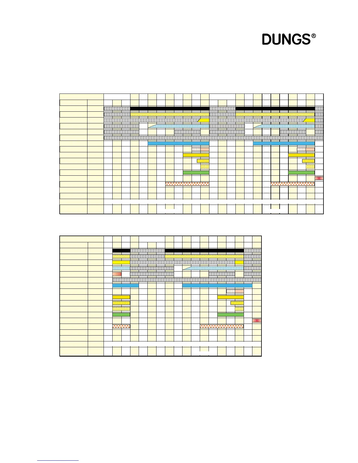
Time diagram
Gas firing, electronic
modulation
Start-up tests
01 02 03 04 05 06 07 08 09
Start-up tests
01 02 03 04 05 06 07 08 09 99
State number
Display
Closed-loop
control sequence
GW max
GW min
Air pressure switch
Flame
GW VPS
Blower motor
Ignition
Valve Y1
Valve Y2
Valve Y3
Operation
Fault
Watchdog
SAD air
SAD gas
VPS flag
Duration
Input
Input
Input
Input
Input
Input
Output
Output
Output
Output
Output
Output
Output
Output
I / O
I / O
Flag
TEST
L G 1 2 3 4 5 6 7 8 9
TEST
L G 1 2 3 4 5 6 7 8 9 F xxh
<3
s
--->Ref
Ref.
P9P9-->P9 P9 P9 -->P0 P0 P0
–––
––– –––
--->Ref
Ref. Ref. Ref.
Ref.
->109° 109° P0-->P0 P0 P0
2*
3*
<3,5
s
<3,5
s
1
s
<30
s
<10
s
5 0,3 5..55 <30
s
1..2
s
2..5
s
10..60s
disregarded
4*
2*
3*
<3
s
--->Ref
Ref.
P9P9-->P9 P9 P9 -->P0 P0 P0
–––
––– –––
--->Ref
Ref. Ref. Ref.
Ref.
->109° 109° P0-->P0 P0 P0
<3,5
s
<3,5
s
1
s
<30
s
<10
s
5 0,3 5..55 <30
s
1..2
s
2..5
s
10..60s
–––
–––
>---> 12 12 21
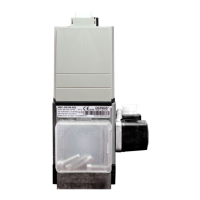
Start-up tests
01 02 03 04 05 06 07 08 09 21 99
State number
Display
Closed-loop
control sequence
GW max
GW min
Air pressure switch
Flame
GW VPS
Blower motor
Ignition
Valve Y1
Valve Y2
Valve Y3
Operation
Fault
Watchdog
SAD air
SAD gas
VPS flag
Duration
Input
Input
Input
Input
Input
Input
Output
Output
Output
Output
Output
Output
Output
Output
I / O
I / O
Flag
12
12
TEST
L G 1 2 3 4 5 6 7 8 9 F xxh
>--->
>--->
>--->
>--->
>--->
>--->
>--->
>--->
>--->
>--->
>--->
>--->
>--->
>--->
>--->
>--->
<3
s
--->Ref
Ref.
P9P9-->P9 P9 P9 -->P0 P0 P0
--->Ref
Ref. Ref. Ref.
Ref.
P1-P9
->109° 109° -->P0 P0 P0 P0
–––
–––
2*
3*
<3,5
s
<3,5
s
1
s
<30
s
<10
s
5 0,3 5..55 <30
s
1..2
s
2..5
s
<24
h
2
s
10..60s
disregarded
–––
–––
P1-P9
––– –––
P1-P9 P1-P9
––– ––– –––
2
s
<1
s
Start without flame after start-up safety period
1 restart permitted, valve proving system inactive
Flame failure during operation
1 restart permitted, valve proving system inactive